Pass Your Juniper JN0-648 Exam Easy!
Juniper JN0-648 Exam Questions & Answers, Accurate & Verified By IT Experts
Instant Download, Free Fast Updates, 99.6% Pass Rate
Juniper JN0-648 Exam Screenshots
Juniper JN0-648 Practice Test Questions, Exam Dumps
Juniper JN0-648 (Enterprise Routing and Switching, Professional (JNCIP-ENT)) exam dumps vce, practice test questions, study guide & video training course to study and pass quickly and easily. Juniper JN0-648 Enterprise Routing and Switching, Professional (JNCIP-ENT) exam dumps & practice test questions and answers. You need avanset vce exam simulator in order to study the Juniper JN0-648 certification exam dumps & Juniper JN0-648 practice test questions in vce format.
Mastering Juniper JN0-648 Layer 2 Technologies and Switching
The Juniper Networks Certified Professional Enterprise Routing and Switching (JNCIP-ENT) certification validates a deep understanding of advanced networking principles. A significant portion of the JN0-648 exam focuses on sophisticated Layer 2 technologies that form the bedrock of modern enterprise networks. Mastery of these topics is not just about memorizing commands but about understanding the underlying mechanisms that ensure a resilient, secure, and scalable network infrastructure. This section delves into key Layer 2 concepts, including Q-in-Q tunneling, Spanning Tree Protocols like MSTP, network access control with 802.1X, and flexible VLAN assignment methods, providing a comprehensive overview for JN0-648 candidates.
These technologies address common enterprise challenges. Q-in-Q allows service providers to transparently tunnel customer VLAN traffic across their own network. Spanning Tree Protocol prevents catastrophic loops in redundant switched topologies. Meanwhile, 802.1X provides a robust framework for authenticating devices as they connect to the network, and filter-based VLANs offer a dynamic way to segment traffic based on more than just the physical port. A thorough grasp of their operation and configuration within Junos OS is critical for success in the JN0-648 examination and in real-world network engineering roles that demand a high level of expertise.
Understanding Q-in-Q Tunneling for JN0-648
Q-in-Q tunneling, formally standardized as IEEE 802.1ad, is a technique used primarily by service providers to extend a Layer 2 Ethernet network for their customers across a provider's backbone. It works by encapsulating customer VLAN frames (C-VLANs) inside a service provider VLAN frame (S-VLAN). This creates a "tunnel" where the entire customer frame, including its original 802.1Q tag, becomes the payload of the provider's frame. This method is invaluable because it allows multiple customers to use the same VLAN IDs without any conflict, as the provider's network only makes forwarding decisions based on the outer S-VLAN tag.
For the JN0-648 exam, it's crucial to understand the configuration syntax on Junos devices. The configuration often involves specifying an interface as a C-VLAN trunk and mapping a range of customer VLAN IDs to a single service provider S-VLAN ID. For instance, a question might present a configuration where customer VLANs 100 through 200 are mapped to a service provider's S-VLAN 10. In this case, any frame arriving with a C-VLAN tag between 100 and 200 would have a new S-VLAN tag of 10 pushed onto its header before being forwarded through the provider network.
The provided sample question illustrates a typical JN0-648 scenario. The configuration would show an interface with a vlan-id-list specifying the range of C-VLANs and a mapping statement associating them with an outer vlan-id. The correct interpretation is that the customer traffic, identified by the inner C-VLAN tags, is encapsulated with the specified outer S-VLAN tag. Therefore, for a configuration mapping VLANs 100-200 to an outer tag of 10, the C-VLANs 100-200 are treated as the inner tag, and the S-VLAN 10 is the outer tag used for transport across the provider network.
Troubleshooting Q-in-Q involves verifying interface modes and VLAN mappings. Commands like show vlans and show ethernet-switching interface are essential. An engineer must ensure that the interfaces facing the customer are configured to accept tagged C-VLAN frames and that the interfaces on the provider backbone are correctly configured to handle the S-VLAN. Misconfigurations can lead to traffic being dropped, as the provider's switches will not recognize the C-VLAN tags if they are not properly encapsulated. Understanding this encapsulation and de-encapsulation process is fundamental for the JN0-648 certification.
Spanning Tree Protocol: Focus on MSTP
Spanning Tree Protocol (STP) and its variants are fundamental to preventing Layer 2 loops in networks with redundant paths. While older versions like STP and RSTP exist, the Multiple Spanning Tree Protocol (MSTP), or IEEE 802.1s, is a key topic for the JN0-648 exam due to its scalability and efficiency. MSTP allows an administrator to group multiple VLANs into a single Spanning Tree instance, known as a Multiple Spanning Tree Instance (MSTI). This significantly reduces the number of STP instances that a switch CPU must process, compared to protocols like VSTP that run one instance per VLAN.
For MSTP to function correctly, several parameters must be identical on all switches that are intended to be part of the same MSTP region. These critical parameters are the configuration name (region name), the configuration revision number, and the MSTI-to-VLAN mapping table. If any of these three elements do not match between two switches, they will consider each other to be in different regions. This distinction is vital because intra-region and inter-region STP behavior differs, potentially leading to suboptimal forwarding paths or even network loops if not configured correctly. The exam often tests this specific knowledge.
A typical JN0-648 question might present configuration snippets from two different switches and ask why they are not in the same MSTP region. As seen in the sample question, even if the region name and revision number match, a mismatch in the VLANs assigned to a specific MSTI will cause a region boundary to form. For example, if Switch A maps VLANs 1-10 to MSTI 1 and Switch B maps VLANs 11-20 to MSTI 1, they cannot be in the same region. This strict requirement ensures consistent logical topology calculations across all switches within a region.
Properly configuring MSTP involves defining the region name and revision number under the [edit protocols mstp] hierarchy. Subsequently, one must define the MSTIs and map the corresponding VLANs to them. Verification is performed using commands like show spanning-tree mstp configuration to check the local settings and show spanning-tree bridge to view the operational status and identify the root bridge for each instance. Understanding how to diagnose a region mismatch is a practical skill that the JN0-648 exam aims to validate, ensuring candidates can build stable and efficient Layer 2 domains.
Network Access Control with 802.1X
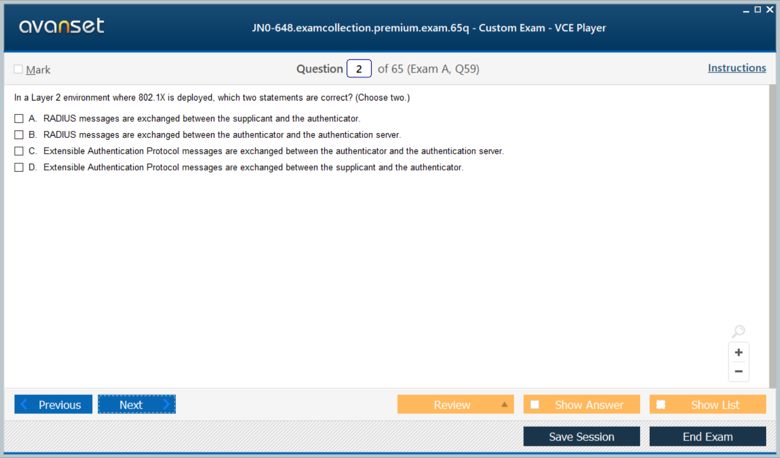
Network access control is a cornerstone of enterprise security, and IEEE 802.1X is the standard for port-based authentication. The JN0-648 exam expects a detailed understanding of its components and operation. The three main components are the supplicant (the client device seeking access), the authenticator (the switch or access point), and the authentication server (typically a RADIUS server). The process begins when a supplicant connects to a port on the authenticator. The port is initially in an unauthorized state, blocking all traffic except for Extensible Authentication Protocol (EAP) messages used for authentication.
The authenticator facilitates the EAP exchange between the supplicant and the authentication server. It packages the supplicant's EAP messages within RADIUS packets and sends them to the server. The server then processes the credentials and sends back a RADIUS Access-Accept or Access-Reject message to the authenticator. If the message is Access-Accept, the authenticator transitions the port to an authorized state, allowing normal data traffic to flow. If it is Access-Reject, the port remains unauthorized. This entire process ensures that only trusted and verified devices can gain access to the network.
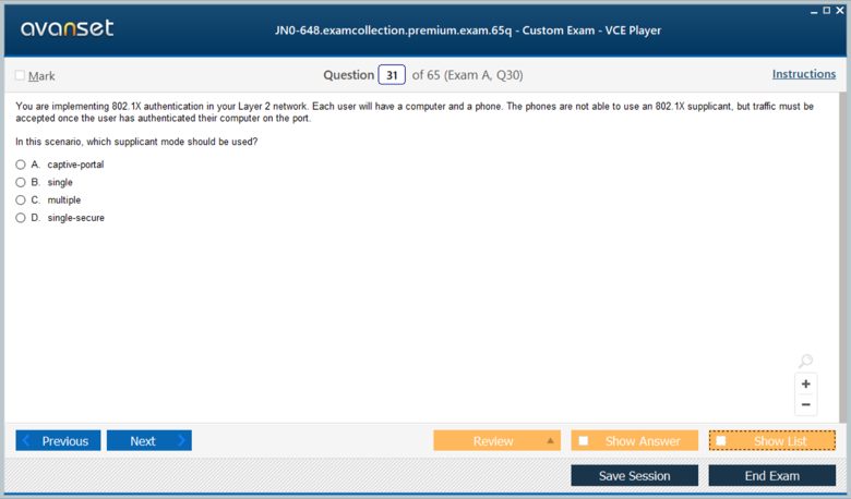
A common challenge in real-world deployments, and a likely topic for a JN0-648 question, is handling devices that do not support 802.1X, such as printers or older equipment. In this scenario, the supplicant will not respond to the EAP messages sent by the authenticator. By default, the authenticator will continue sending EAP request messages for a configured period. If no response is received after a certain number of retries, a fallback mechanism can be triggered. This could involve placing the port into a specific guest VLAN with limited access or using MAC RADIUS authentication as an alternative.
The key takeaway is that the authenticator (the switch) drives this process. When a non-802.1X-capable device connects, the switch sends EAP requests but gets no reply. After its internal timers expire, it takes a pre-configured action. A common configuration is to eventually allow traffic, often into a restricted VLAN, to support these legacy devices. Understanding how to configure these fallback mechanisms on Junos devices using features like mac-radius or guest-vlan is essential knowledge for any professional managing an enterprise network and for passing the JN0-648 exam.
Flexible Traffic Management with Filter-Based VLANs
Traditional VLAN assignment is static; a switch port is configured to belong to a specific VLAN, and all traffic entering that port is placed into that VLAN. However, modern enterprise networks often require more dynamic and flexible traffic segmentation. This is where filter-based VLANs (FBV) become incredibly useful. FBV, a key topic for the JN0-648, allows a network administrator to assign traffic to a VLAN based on the properties of the packet itself, rather than the physical port on which it arrived. This provides a powerful method for policy-based traffic classification.
The mechanism works by applying a firewall filter to a switch port. This filter is configured with match conditions that inspect various fields within the packet header, such as the source IP address, destination IP address, protocol type, or source/destination port numbers. When a packet entering the port matches the filter's criteria, a specified action is taken. For FBV, the action is to forward the packet into a particular VLAN. This allows for granular control, enabling devices on the same physical switch port to be placed into different logical network segments.
Consider a scenario presented in a JN0-648 question where a company needs to sort traffic from an unmanaged switch into different VLANs based on the source IP address. This is a perfect use case for filter-based VLANs. An administrator would configure a firewall filter on the ingress port of their managed EX Series switch. The filter would contain terms, each matching a specific IP subnet and directing that traffic to the appropriate VLAN. For example, all traffic from the 192.168.10.0/24 subnet could be assigned to VLAN 10 (Sales), while traffic from 192.168.20.0/24 is assigned to VLAN 20 (Engineering).
This technique is particularly useful for environments with unmanaged downstream switches or for sorting traffic from devices like IP phones and computers that share a single network drop. Configuration involves defining the VLANs, creating a firewall filter under the [edit firewall family ethernet-switching] hierarchy with an action of vlan
Deep Dive into JN0-648 Interior Gateway Protocols
An essential domain for any professional-level networking certification, including the JN0-648, is the mastery of Interior Gateway Protocols (IGPs). IGPs are the engines that power routing within an autonomous system (AS), enabling routers to learn about network topology and calculate the best paths for data to travel. While various IGPs exist, the JNCIP-ENT exam places a strong emphasis on OSPF (Open Shortest Path First) and IS-IS (Intermediate System to Intermediate System). A candidate must not only understand their fundamental operations but also their advanced features, scalability mechanisms, and nuanced configuration details within the Junos OS.
This exploration will cover the architectural components, operational states, and key functionalities of both OSPF and IS-IS as they pertain to the JN0-648 curriculum. We will dissect OSPF area types and router roles, explaining how they contribute to a hierarchical and efficient network design. Similarly, we will investigate the two-level hierarchy of IS-IS, the function of its Protocol Data Units (PDUs), and the practical implications of advanced features like the overload bit. By examining these protocols in detail, candidates can build the robust knowledge base required to tackle complex routing scenarios on the JN0-648 exam and in sophisticated enterprise environments.
OSPF Architecture and Router Roles
OSPF is a link-state routing protocol that uses the Dijkstra Shortest Path First (SPF) algorithm to calculate loop-free paths. Its hierarchical design is one of its most powerful features, allowing it to scale in large enterprise networks. This hierarchy is built around the concept of areas. An OSPF network is divided into multiple areas, all of which must connect to a central backbone area, designated as Area 0. This design limits the scope of link-state advertisements (LSAs) and reduces the SPF calculation overhead on routers, as routers only need to maintain a complete topological database for their own area.
Within this architecture, routers assume specific roles based on their location in the topology. A router with all its interfaces in a single, non-backbone area is known as an internal router. A router connected to two or more different areas, one of which must be Area 0, is called an Area Border Router (ABR). ABRs are critical as they are responsible for summarizing routing information from non-backbone areas and advertising it into the backbone, and vice-versa. This summarization is key to OSPF's scalability. This is a common topic for JN0-648 questions.
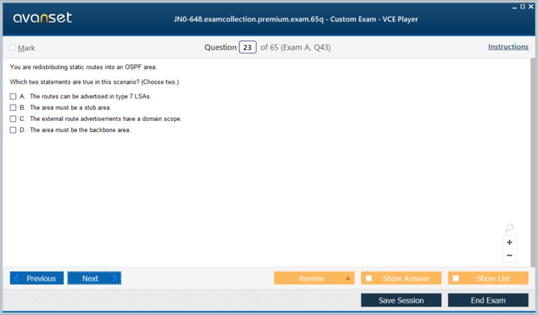
Another crucial role is the Autonomous System Boundary Router (ASBR). An ASBR is a router that connects the OSPF domain to an external network running a different routing protocol, such as BGP or another IGP. This router is responsible for redistributing routes from the external domain into OSPF, which are then propagated as Type 5 external LSAs. A JN0-648 exam question might present the output of a show ospf database command and require the candidate to identify a router's role. If the output shows LSAs for both Area 0 and another area, the router is definitively an ABR.
The sample question highlights this exact scenario. Seeing LSAs for Area 0.0.0.0 and Area 0.0.0.10 in the OSPF database is a clear indicator that the local router is an ABR. It sits on the border of the backbone and area 10, performing the essential function of linking the two. Understanding how to interpret the OSPF database to identify ABRs, ASBRs, and different LSA types is a fundamental skill for any JNCIP-ENT candidate and demonstrates a practical ability to analyze and troubleshoot a complex OSPF environment.
Understanding IS-IS Levels and the Overload Bit
IS-IS, like OSPF, is a link-state IGP that uses the SPF algorithm for path calculation. It was originally designed for the CLNS protocol suite but was extended to support IP routing, known as Integrated IS-IS. A core concept in IS-IS, crucial for the JN0-648 exam, is its two-level hierarchy, which is analogous to the OSPF backbone and non-backbone area structure. Routers in IS-IS can be Level 1 (L1), Level 2 (L2), or both (L1/L2). L1 routers handle intra-area routing, while L2 routers handle inter-area routing, forming a backbone.
L1 routers only form adjacencies with other L1 or L1/L2 routers within the same area. They maintain a link-state database (LSDB) only for their own area and use a default route pointing to the nearest L1/L2 router to reach destinations in other areas. L2 routers form a contiguous backbone and maintain an LSDB for the inter-area topology. An L1/L2 router participates in both levels, maintaining separate LSDBs for each. It acts as the gateway for its area, advertising intra-area reachability into the L2 backbone and providing the default route for L1 routers.
A particularly important feature tested in the JN0-648 is the IS-IS overload bit. When a router sets the overload bit in its Link State PDUs (LSPs), it is signaling to all other routers in the IS-IS domain that it should not be used for forwarding transit traffic. Other routers will still see the overloaded router in their LSDB, but when they run their SPF calculation, they will avoid paths that traverse it. However, traffic destined for the overloaded router's own directly connected prefixes is not affected and will still be routed to it.
This mechanism is extremely useful for network maintenance. An administrator can set the overload bit before taking a router offline for an upgrade or repair. This gracefully diverts traffic away from the router without causing an abrupt network reconvergence, preventing traffic loss. Once the maintenance is complete, the bit is cleared, and the router seamlessly resumes its role in forwarding transit traffic. The primary effect, as the sample question points out, is that the local device will no longer be used for transit traffic, making it a powerful tool for controlled network changes.
IS-IS Adjacencies and Protocol Data Units (PDUs)
Unlike OSPF, which runs directly over IP, IS-IS communicates using its own Protocol Data Units (PDUs) encapsulated directly in Layer 2 frames. Understanding these PDUs and the process of forming adjacencies is critical for the JN0-648 exam. The primary PDU types are Hello PDUs, Link State PDUs (LSPs), and Sequence Number PDUs (SNPs). Hello PDUs are used to discover neighbors and establish and maintain adjacencies. On broadcast links like Ethernet, there are separate L1 and L2 Hello PDUs to establish level-specific adjacencies.
The adjacency formation process involves a three-way handshake on broadcast networks to elect a Designated Intermediate System (DIS). The DIS is similar to OSPF's Designated Router (DR) and is responsible for generating a special LSP called a pseudonode LSP on behalf of the broadcast segment. This reduces the number of adjacencies and LSPs required on the segment, improving scalability. The DIS election is based on priority, with the MAC address used as a tiebreaker. All other routers on the segment form adjacencies only with the DIS.
Once adjacencies are formed, routers exchange their LSPs to build their link-state databases. LSPs contain information about the router's neighbors and reachable prefixes. When a router receives an LSP, it floods it to all its other neighbors until all routers in the area (for L1) or the backbone (for L2) have a synchronized database. To manage this process, IS-IS uses Complete Sequence Number PDUs (CSNPs) and Partial Sequence Number PDUs (PSNPs). CSNPs contain a summary of all LSPs in the DIS's database and are sent periodically.
PSNPs are used to acknowledge the receipt of LSPs and to request missing or more recent LSPs. This robust mechanism ensures that the LSDBs across all routers remain consistent. For the JN0-648, a candidate should be familiar with troubleshooting IS-IS adjacencies using commands like show isis adjacency and inspecting the database with show isis database. Common issues include mismatched area IDs, incorrect interface levels, or MTU mismatches, all of which can prevent adjacencies from forming correctly.
Comparing OSPF and IS-IS for the JNCIP-ENT
While both OSPF and IS-IS are link-state IGPs that achieve similar goals, the JN0-648 exam expects candidates to know their key differences in design and operation. One of the most fundamental differences is their transport mechanism. OSPF is encapsulated in IP packets (protocol 89), making it dependent on the IP stack. IS-IS, on the other hand, operates at Layer 2.5, encapsulating its PDUs directly within Layer 2 frames. This makes IS-IS protocol-agnostic, which is why it was easily extended to support both CLNS and IP (becoming Integrated IS-IS).
Their hierarchical structures also differ. OSPF uses a strict two-level hierarchy centered on the backbone area (Area 0). All other areas must connect directly to Area 0, and traffic between two non-backbone areas must traverse the backbone. IS-IS has a more flexible two-level hierarchy with Level 1 for intra-area routing and Level 2 for the backbone. The L2 backbone can be partitioned, and L1 areas are less strictly defined. This can sometimes make IS-IS designs simpler and more flexible in certain topologies compared to OSPF's rigid backbone requirement.
Another key difference lies in their extensibility. IS-IS was designed using a Type-Length-Value (TLV) structure for its PDUs. This makes it incredibly easy to add new features and capabilities to the protocol without needing to redesign the fundamental PDU format. New functionality can simply be added as a new TLV. OSPF, while also extensible through Opaque LSAs, has historically been seen as slightly more rigid. The TLV-based design of IS-IS is a major reason why it has been readily adapted for modern technologies like MPLS Traffic Engineering and TRILL.
For the enterprise-focused JN0-648, OSPF is more commonly encountered, but IS-IS is prevalent in large service provider networks and is gaining traction in large data centers. A JNCIP-ENT professional should be comfortable with both. Understanding their respective strengths—OSPF's widespread adoption and familiarity versus IS-IS's scalability and extensibility—is crucial. The ability to choose the right protocol for a given network design, and to configure and troubleshoot it effectively in Junos OS, is a hallmark of the expertise the JN0-648 certification represents.
Advanced IP Multicast for the JN0-648 Exam
IP multicast is a network efficiency technology that allows a single source to send a data stream to multiple interested recipients simultaneously, without having to send an individual copy of the data to each one. This one-to-many communication model is essential for applications like IPTV, video conferencing, financial data feeds, and online gaming. The JN0-648 exam requires a deep understanding of multicast concepts, particularly the Protocol Independent Multicast (PIM) routing protocol, which is the de facto standard for routing multicast traffic across an IP network.
This section will provide a comprehensive review of PIM, focusing on the modes and mechanisms most relevant to the JNCIP-ENT curriculum. We will explore the operation of PIM Sparse Mode (PIM-SM), the roles of the Rendezvous Point (RP), and the transition from a shared tree to a Shortest Path Tree (SPT). We will also dedicate significant attention to PIM Source-Specific Multicast (SSM), a more modern and simplified model that enhances security and reduces complexity. A solid grasp of these topics, including their configuration and verification in Junos OS, is vital for success on the JN0-648 exam.
PIM Sparse Mode (PIM-SM) Fundamentals
PIM Sparse Mode is the most widely deployed multicast routing protocol and a central topic for the JN0-648. It is designed for networks where multicast group members are sparsely distributed, and it operates on an explicit join model. This means that multicast traffic is only forwarded to network segments where there are active receivers that have explicitly requested to join a multicast group. This is in contrast to dense mode, which uses a flood-and-prune approach and is less efficient for most modern applications.
The operation of PIM-SM revolves around a special router called the Rendezvous Point (RP). The RP acts as a meeting point for sources and receivers of a particular multicast group. When a receiver wants to join a group, its local router (the Designated Router, or DR) sends a PIM Join message hop-by-hop towards the RP for that group. This creates a branch of a shared distribution tree, also known as an RP-Tree (RPT), which is rooted at the RP. All routers along this path will now forward traffic for that group towards the receiver.
Simultaneously, when a multicast source starts sending traffic, its DR encapsulates the initial multicast packets into PIM Register messages and sends them directly to the RP. The RP then de-encapsulates these packets and forwards them down the shared RPT to any active receivers. This ensures that sources and receivers can find each other without the source needing to know where the receivers are, and vice-versa. The RP is the crucial intermediary that makes this initial connection possible. Understanding the role of the RP is fundamental for the JN0-648.
The process of discovering the RP can be done statically, by configuring the RP address on every multicast router, or dynamically using protocols like Bootstrap Router (BSR). Once the initial connection is made via the RP, the protocol has a mechanism to optimize the data path, which is known as the SPT switchover. This efficient, explicit-join model makes PIM-SM highly scalable and suitable for the large, complex networks typical of the enterprise environments targeted by the JNCIP-ENT certification.
The Shared Tree to Shortest Path Tree (SPT) Switchover
While the Rendezvous Point and the shared tree (RPT) are excellent for allowing sources and receivers to discover each other, the path from the source to the receiver via the RP may be suboptimal. For high-bandwidth applications, it is more efficient for traffic to follow the shortest unicast path from the source directly to the receiver. PIM-SM includes a mechanism to transition from the shared tree to a Source-Specific or Shortest Path Tree (SPT). This SPT switchover is a key concept for the JN0-648 exam.
The process is initiated by the receiver's Designated Router (DR). Once the DR starts receiving multicast traffic for a group via the RPT, it learns the unicast IP address of the original source from the packet headers. By default, on Junos devices, the DR will immediately initiate the switchover. It sends a PIM Join message directly towards the source of the multicast traffic. This join message travels hop-by-hop, following the unicast routing path, creating a new distribution tree branch rooted at the source itself.
As this new SPT branch is being built, multicast traffic from the source will start arriving via this more direct path. Once the receiver's DR starts receiving the traffic on the SPT, it no longer needs the feed from the shared tree. To stop the duplicate stream, the DR sends a PIM Prune message up the shared tree towards the RP. This prune message signals to the upstream routers that traffic for this specific source and group is no longer needed on this branch of the RPT.
The sample JN0-648 question describes this exact scenario. After the formation of the shortest-path tree, a join message is sent from the receiver's router (R2) directly to the source's router (R1) to build the SPT. Subsequently, a prune message would be sent from R2 towards the RP (R5) to tear down the flow from the shared tree. This two-step process ensures an optimal, low-latency path for multicast traffic while maintaining the scalability of the PIM-SM discovery mechanism. Mastering the logic of this switchover is critical for any JNCIP-ENT candidate.
Understanding PIM Source-Specific Multicast (SSM)
Source-Specific Multicast (SSM) is an evolution of PIM that simplifies multicast deployment and improves security. Unlike traditional PIM-SM which uses the (*,G) notation (any-source, group), SSM relies on (S,G) channels, where S is the specific source address and G is the group address. In the SSM model, a receiver must know the exact IP address of the source it wishes to receive traffic from. When a receiver joins a group, it specifies both the source and group address. This eliminates the need for a Rendezvous Point altogether.
The IANA has reserved the IP address range 232.0.0.0/8 specifically for SSM applications. When a router receives an IGMPv3 or PIM join for a group within this range, it knows to operate in SSM mode. Since the source is known, the router can immediately send a PIM (S,G) Join message directly towards the source, following the unicast path. This immediately builds the shortest path tree from the source to the receiver without any of the complexity of RPs, shared trees, or SPT switchovers. This simplicity is a major advantage of SSM.
A common challenge, often tested on the JN0-648, is when an application needs to use SSM but is hard-coded to use a multicast group address outside the standard 232.0.0.0/8 range. For example, a source might use 235.44.123.100. In this case, routers will not automatically treat it as an SSM group. To resolve this, the network administrator must explicitly configure the routers to recognize this group as an SSM group. This is done in Junos OS using an SSM map policy.
The ssm-map configuration, located under the [edit routing-options multicast] hierarchy, allows an administrator to define a policy that maps a specific multicast group address (or range) to a source address, effectively telling the router to treat joins for this group as SSM joins. As the sample question suggests, to fix a non-functional PIM-SSM feed for an address outside the 232/8 range, one solution is to reconfigure the source to use an address within the standard range. The alternative, and often more practical solution, is to create an ssm-map to enable SSM processing for the non-standard address.
Configuring and Verifying Multicast in Junos OS
For the JN0-648 exam, practical knowledge of Junos OS configuration and verification is paramount. To enable multicast, PIM must be configured on all interfaces that will participate in multicast routing, both towards sources and receivers. This is done under the [edit protocols pim] hierarchy. For PIM-SM, the address of the Rendezvous Point must be configured on all PIM routers. This can be a static configuration pointing to the RP's address or a dynamic configuration using BSR.
Configuration for a receiver-facing interface would typically include [edit protocols pim interface ge-0/0/1 mode sparse] and [edit protocols igmp interface ge-0/0/1]. IGMP (Internet Group Management Protocol) is used by hosts to signal their interest in joining a multicast group to their local router. On the source-facing interfaces, only PIM needs to be enabled. It is also important to ensure that unicast routing is functioning correctly, as PIM relies on the unicast routing table to find the path towards sources and RPs.
Verification is a key skill for troubleshooting multicast issues. The command show pim neighbors is used to verify that PIM adjacencies have been formed between routers. To check the status of the RP, one can use show pim rps. The most important command for troubleshooting multicast data flow is show multicast route. This command displays the multicast routing table and shows the upstream and downstream interfaces for a given (S,G) or (*,G) state, allowing an engineer to trace the path of the distribution tree.
For SSM, the configuration is simpler as no RP is required. You simply need to enable PIM on the relevant interfaces. However, if using groups outside the 232/8 range, the ssm-map configuration becomes essential. Verification would involve checking the multicast route table for an (S,G) entry rather than a (*,G) entry. A JNCIP-ENT professional must be adept at using these commands to quickly diagnose and resolve common multicast problems, such as joins not reaching the RP, SPTs failing to build, or traffic not being forwarded down the correct interfaces.
EVPN-VXLAN and Data Center Fabric for JN0-648
Modern enterprise networks, particularly within data centers, are rapidly evolving away from traditional Layer 2 designs. The need for scalability, multitenancy, and workload mobility has driven the adoption of overlay technologies. The premier solution in this space, and a major topic on the JN0-648 exam, is Ethernet VPN (EVPN) with a Virtual Extensible LAN (VXLAN) data plane. This architecture provides Layer 2 adjacency over a Layer 3 underlay network, effectively decoupling the logical network from the physical infrastructure.
This part will explore the core components and operational principles of EVPN-VXLAN, tailored to the knowledge required for the JNCIP-ENT certification. We will examine the roles of the underlay and overlay, the function of VXLAN Network Identifiers (VNIs) and VXLAN Tunnel Endpoints (VTEPs), and the use of BGP as the control plane for EVPN. We will also touch upon advanced concepts featured in the JN0-648, such as Junos Fusion architecture and the different EVPN route types used for MAC address learning, ARP suppression, and multihoming.
Core Concepts of EVPN-VXLAN
At its heart, EVPN-VXLAN is an overlay technology. It creates logical Layer 2 networks that are tunneled over a physical Layer 3 network, known as the underlay. The underlay's only job is to provide robust IP connectivity between the network devices. This is typically achieved using a well-established IGP like OSPF or BGP. The physical switches participating in the VXLAN fabric are called VXLAN Tunnel Endpoints (VTEPs). These devices are responsible for encapsulating and de-encapsulating traffic.
When a Layer 2 frame from a virtual machine or server enters a VTEP, the VTEP encapsulates it within a VXLAN header, which is then placed inside a standard UDP/IP packet. The VXLAN header contains a 24-bit VXLAN Network Identifier (VNI), which is analogous to a VLAN ID but offers a much larger namespace (over 16 million possibilities). This allows for massive scalability and multitenancy. The outer IP header uses the source IP of the local VTEP and the destination IP of the remote VTEP where the destination MAC address resides. This IP packet is then routed normally across the Layer 3 underlay.
The magic of this architecture lies in the control plane, which is where EVPN comes in. EVPN uses extensions to the BGP protocol to distribute Layer 2 MAC address and Layer 3 IP address reachability information between VTEPs. Instead of relying on inefficient flood-and-learn mechanisms like traditional Ethernet, a VTEP learns a local MAC address and advertises it, along with its own IP address and the associated VNI, to all other VTEPs using a BGP update. This "conversation-based" learning is far more scalable and efficient. This foundational knowledge is essential for the JN0-648.
One of the key configuration elements, highlighted in a sample JN0-648 question, is linking the logical segments. Within a Junos device, a traditional VLAN or bridge domain must be explicitly mapped to a VNI. Without the statement set bridge-domains BD-101 vxlan vni 101, the device knows about VLAN 101 and knows about VNI 101, but it doesn't know they are part of the same logical Layer 2 segment. This mapping is what ties the overlay VNI to the local bridging domain, enabling the encapsulation process.
The Role of BGP as the EVPN Control Plane
The use of BGP as the control plane is what makes EVPN so powerful and scalable. MP-BGP (Multi-Protocol BGP) was enhanced with a new Address Family Identifier (AFI) and Subsequent Address Family Identifier (SAFI) specifically for EVPN. This allows BGP to carry not just traditional IP prefixes, but also MAC addresses, MAC/IP bindings, and other information needed to build the overlay network. The JN0-648 exam requires familiarity with the key EVPN route types that BGP distributes.
The most important route types are Type 1, Type 2, and Type 3. A Type 2 route, or MAC/IP Advertisement route, is the workhorse of EVPN. When a VTEP learns a new MAC address on a local port, it advertises this MAC address, often along with its corresponding IP address, in a Type 2 route. This route is sent to all other VTEPs, which then install this information in their forwarding tables. This allows for targeted unicast forwarding across the VXLAN tunnels instead of flooding.
A Type 3 route, or Inclusive Multicast Ethernet Tag route, is used to handle Broadcast, Unknown Unicast, and Multicast (BUM) traffic. Instead of flooding BUM traffic everywhere, EVPN uses Type 3 routes to build multicast trees within the underlay for each VNI. This provides a much more efficient way to forward BUM traffic to only those VTEPs that are participating in a given VNI. This avoids the broadcast storms that can plague large traditional Layer 2 domains.
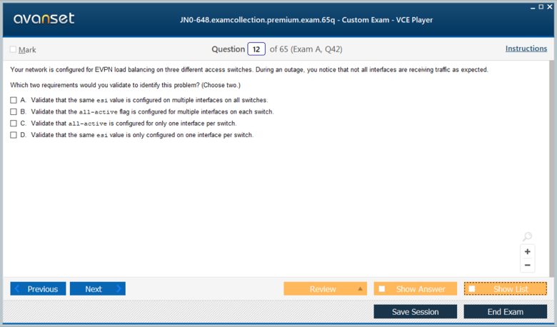
A Type 1 route, the Ethernet Auto-Discovery (A-D) route, is critical for multihoming scenarios. When a single server or switch is connected to two or more VTEPs for redundancy (a setup known as an Ethernet Segment), the VTEPs advertise a Type 1 route for that Ethernet Segment Identifier (ESI). This allows remote VTEPs to learn about all the paths to that segment. As the sample JN0-648 question implies, if a link on the ESI goes down, the corresponding VTEP withdraws its Type 1 route, signaling to others that this path is no longer valid, enabling fast traffic rerouting.
Junos Fusion Enterprise Architecture
Junos Fusion Enterprise is an architecture designed to simplify network management by allowing multiple, physically separate switches to be managed as a single logical device. This is highly relevant in data center and large campus environments. The architecture consists of one or more Aggregation Devices (AD), which act as the central management and control plane, and numerous Satellite Devices (SD), which are essentially remote line cards providing port connectivity. The JN0-648 exam may include scenarios based on this architecture.
The aggregation device, typically a high-end MX router or QFX/EX switch, runs the Junos OS and holds the entire configuration for the Fusion fabric. The satellite devices, such as QFX5100 or EX4300 switches, run a lightweight software version that allows them to connect to and be managed by the AD. All configuration, monitoring, and troubleshooting for the entire fabric, including all ports on the SDs, is performed from the single AD. This dramatically reduces operational complexity.
An important feature within this architecture is local switching. When local switching is enabled on a satellite device, the SD is capable of forwarding Layer 2 traffic directly between its own ports (known as extended ports) without having to send the traffic up to the aggregation device. This is highly efficient for traffic that is localized to a single access switch, as it reduces latency and conserves bandwidth on the uplinks to the AD. The AD still handles all the control plane functions and traffic that needs to be routed or switched to a different SD.
The sample JN0-648 question touches on this behavior. When local switching is enabled and a packet with an unknown destination MAC address (an unknown unicast frame) is received on an SD port, the SD must determine how to forward it. Since it's a BUM frame, standard Layer 2 behavior is to flood it. With local switching, the SD will flood the packet out of all other extended ports on that SD within the same VLAN. It does not need to send the packet to the AD for a forwarding decision, as the local switching capability allows it to handle this function itself.
Troubleshooting EVPN-VXLAN Fabrics
Troubleshooting a modern EVPN-VXLAN fabric requires a different skill set than troubleshooting traditional networks, and the JN0-648 validates these skills. Problems can exist in the underlay, the overlay control plane, or the data plane encapsulation. A systematic approach is essential. The first step is always to verify the underlay. Use standard ping and traceroute tools, as well as show ospf neighbor or show bgp summary (if using BGP for the underlay) to ensure full IP reachability between all VTEP loopback addresses.
Next, verify the overlay control plane. The crucial command is show bgp summary to confirm that the MP-BGP sessions between VTEPs are established. Then, dive deeper with show route table bgp.evpn.0. This table should contain the EVPN routes (Type 1, 2, 3, etc.) being received from other VTEPs. If a remote MAC address is missing from this table, it indicates a BGP advertisement or policy issue. You can check for specific MAC addresses with show route table
Finally, check the data plane. The show vxlan tunnel-end-point command is used to verify the state of the VXLAN tunnels. If control plane learning is working but data is not flowing, there could be an encapsulation issue or a problem in the underlay path, such as an MTU mismatch, which is a common problem in tunnel-based networks. The monitor interface command can be used to see if VXLAN encapsulated packets (on UDP port 4789) are being sent and received. Understanding this layered troubleshooting approach is vital for any JNCIP-ENT professional managing a data center fabric.
Security, Availability, and Services for JN0-648
Beyond the core routing and switching protocols, the JN0-648 JNCIP-ENT exam validates a candidate's expertise in a range of technologies that ensure an enterprise network is secure, highly available, and capable of delivering essential services. This final part covers a selection of these critical topics, including Power over Ethernet (PoE) for powering endpoint devices, high availability mechanisms that prevent network outages, and advanced features of the IS-IS routing protocol. A holistic understanding of these elements is what distinguishes a professional-level engineer.
This concluding section will delve into the practical aspects of managing PoE on Junos devices, exploring different management modes that balance power allocation and efficiency. We will also discuss the importance of high availability features within routing protocols, such as the IS-IS overload bit, which allows for graceful network maintenance. By integrating these concepts with the knowledge from previous sections, a JN0-648 candidate can form a complete picture of what it takes to design, deploy, and maintain a modern, robust, and full-featured enterprise network.
Power over Ethernet (PoE) Management
Power over Ethernet is a ubiquitous technology in modern enterprise networks, enabling switches to deliver electrical power over standard Ethernet cabling to connected devices like wireless access points, IP phones, and security cameras. This simplifies deployment by eliminating the need for a separate power source for each device. The JN0-648 exam expects candidates to be familiar with how PoE is managed on Junos switches. This involves understanding power budgets, device classification, and the different management modes available.
Junos OS provides several modes for managing the allocation of power from a switch's total PoE budget to its individual ports. Two of the most important supported modes are class mode and static mode. In class mode, the switch communicates with the powered device (PD) using the Link Layer Discovery Protocol (LLDP). The PD informs the switch of its IEEE-defined power class (0 through 4), which corresponds to a maximum power requirement. The switch then allocates that amount of power from its budget to the port. This is a dynamic and efficient method.
Static mode, on the other hand, offers a more manual approach. In this mode, the network administrator configures a specific, fixed amount of power that is reserved for a particular port. The switch will guarantee this power allocation to the port, regardless of the class reported by the connected device. This is useful for non-standard or legacy devices that may not correctly report their power class, or for critical devices where you want to ensure a specific amount of power is always reserved, preventing it from being allocated elsewhere even when the device is not connected.
The sample JN0-648 question asks to identify two supported PoE management modes, with the correct answers being class and static. Understanding the difference is key. Class mode is dynamic and based on device standards, making it the preferred method for most deployments. Static mode provides granular, manual control for specific use cases. A professional-level engineer must know when to use each mode to effectively manage the switch's power budget and ensure reliable operation of all connected powered devices.
Graceful Maintenance with the IS-IS Overload Bit
High availability is a critical requirement for any enterprise network. Network downtime can lead to significant productivity and financial losses. Routing protocols play a huge role in maintaining availability, not just by rerouting traffic during failures, but also by providing mechanisms for performing network maintenance without causing disruption. One such mechanism, specific to the IS-IS protocol and a key topic for the JN0-648, is the overload bit. This feature allows an administrator to gracefully remove a router from the forwarding path.
When an administrator needs to perform maintenance on a router, such as a software upgrade or hardware replacement, simply shutting down routing protocols or interfaces can cause an abrupt network reconvergence, potentially leading to traffic black-holing or packet loss while other routers calculate new paths. The overload bit provides a much cleaner solution. When the overload option is configured on an IS-IS router, the router sets a specific bit in its outgoing Link State PDUs (LSPs).
This bit acts as a signal to all other IS-IS routers in the domain. Upon receiving an LSP with the overload bit set, other routers will continue to see the overloaded router and its links in their Link State Database. However, when they perform their SPF (Shortest Path First) calculation to build their routing tables, they will ignore that router as a potential transit hop. The practical effect, as noted in the JN0-648 sample question, is that the local device will no longer be used for transit traffic.
Traffic destined for networks directly connected to the overloaded router will still be routed to it, as it may be the only path. However, all traffic that would have simply passed through the router on its way to another destination will be rerouted onto alternate paths. This allows the administrator to safely perform the required maintenance on an idle router. Once the work is complete, the overload configuration is removed, the bit is cleared, and the router seamlessly resumes its role in forwarding transit traffic. This demonstrates a key high-availability technique expected of a JNCIP-ENT.
Ensuring Loop-Free Topologies with VSTP
While modern data centers are moving towards EVPN-VXLAN, traditional Layer 2 networks based on VLANs and Spanning Tree Protocol are still widely deployed in enterprise campus and access layers. Preventing Layer 2 loops in these networks is paramount. The JN0-648 exam may test knowledge of various STP flavors, including VSTP (VLAN Spanning Tree Protocol). VSTP is a Juniper-proprietary protocol that is compatible with Cisco's Per-VLAN Spanning Tree Plus (PVST+). It maintains a separate Spanning Tree instance for each VLAN.
This per-VLAN approach allows for more granular traffic engineering and load balancing compared to traditional STP or even MSTP in some scenarios. By configuring different root bridges for different VLANs, an administrator can ensure that the forwarding paths for various VLANs are diverse, making better use of available redundant links. For example, VLANs 1-100 could have Switch A as their root bridge, while VLANs 101-200 use Switch B as their root, effectively balancing the traffic load across the network uplinks.
A key operational requirement for VSTP, and a potential pitfall tested in the JN0-648, is that for VSTP to protect a VLAN from loops, that VLAN must be explicitly configured under the VSTP protocol stanza. If you have a Layer 2 domain with VLANs 2 through 300, it is not sufficient to simply enable VSTP globally. You must ensure that all VLANs that are actively trunked across redundant paths are included in the VSTP configuration. If a VLAN is missed, VSTP will not run an instance for it, leaving it completely unprotected from loops.
Therefore, in a scenario where you are using VLANs 2 through 300, the correct approach is to ensure that the configuration under [edit protocols vstp] includes vlan all or a specific vlan-group that encompasses all required VLANs, from 2 to 300. Simply enabling RSTP is not the correct answer, as RSTP runs a single instance for all VLANs and does not provide the per-VLAN load balancing of VSTP. The JN0-648 requires this level of precision in understanding protocol operation and configuration.
Final Preparation Strategy for the JN0-648 Exam
Successfully passing the JN0-648 exam requires a combination of deep theoretical knowledge and hands-on practical skill. The topics covered in this five-part series—advanced Layer 2 switching, OSPF and IS-IS, IP multicast, EVPN-VXLAN, and network services—represent the core domains of the JNCIP-ENT certification. A successful candidate must move beyond basic concepts and understand the intricate details of protocol operation, Junos OS configuration syntax, and effective troubleshooting methodologies for each technology area.
A recommended study plan should involve reviewing official Juniper technical documentation and study guides to build a strong theoretical foundation. This should be immediately followed by extensive hands-on lab practice. Building topologies from scratch, configuring features like Q-in-Q, MSTP, OSPF areas, PIM-SM, and a full EVPN-VXLAN fabric is invaluable. During this practice, focus on using verification and troubleshooting commands to observe protocol behavior. Intentionally breaking configurations and then fixing them is one of the best ways to solidify your understanding.
For example, configure two MSTP switches but intentionally mismatch the MSTI-to-VLAN mapping and observe the result with show spanning-tree bridge. Set up a PIM-SM network and use show multicast route to watch the state change from (*,G) to (S,G) during an SPT switchover. Use show isis adjacency to diagnose why two routers are not becoming neighbors. This active, hands-on learning process is what bridges the gap between knowing about a technology and truly understanding it at the professional level required to earn the JNCIP-ENT and excel in a demanding network engineering role.
Go to testing centre with ease on our mind when you use Juniper JN0-648 vce exam dumps, practice test questions and answers. Juniper JN0-648 Enterprise Routing and Switching, Professional (JNCIP-ENT) certification practice test questions and answers, study guide, exam dumps and video training course in vce format to help you study with ease. Prepare with confidence and study using Juniper JN0-648 exam dumps & practice test questions and answers vce from ExamCollection.


Top Juniper Certifications


Top Juniper Certification Exams
Site Search:


