


Study Guide
521 PDF Pages
$27.49$24.99
CWNP CWDP-303 Exam Questions & Answers, Accurate & Verified By IT Experts
Instant Download, Free Fast Updates, 99.6% Pass Rate
CWNP CWDP-303 Exam Screenshots
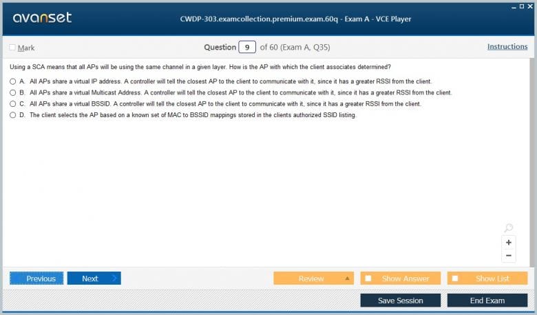
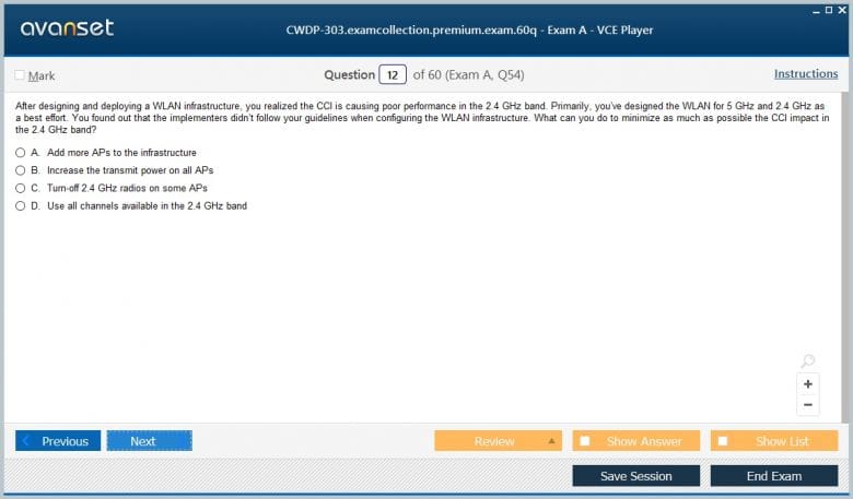
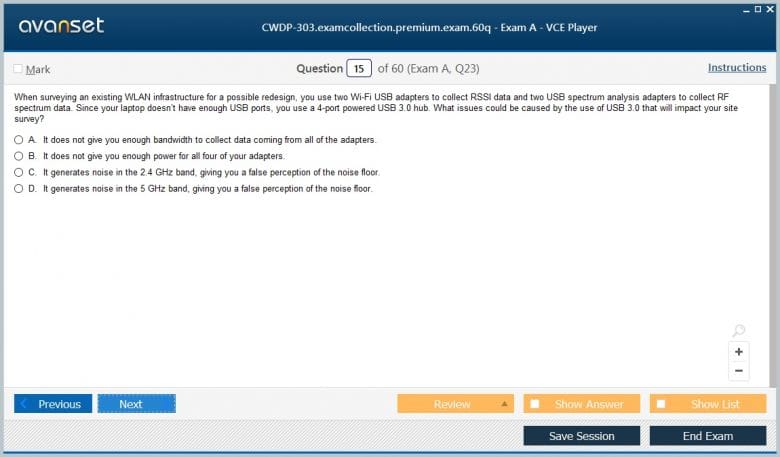
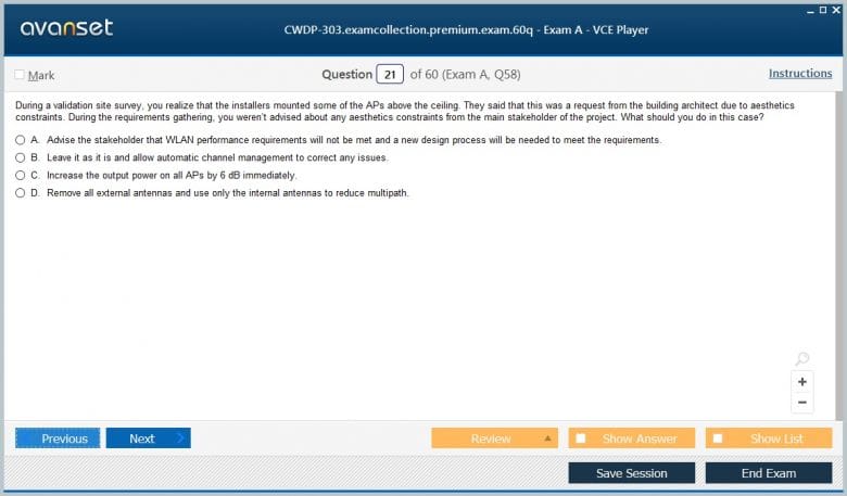
CWNP CWDP-303 Practice Test Questions in VCE Format
| File | Votes | Size | Date |
|---|---|---|---|
File CWNP.Actualtests.CWDP-303.v2019-04-01.by.George.28q.vce |
Votes 4 |
Size 40.35 KB |
Date Apr 02, 2019 |
CWNP CWDP-303 Practice Test Questions, Exam Dumps
CWNP CWDP-303 (Certified Wireless Design Professional) exam dumps vce, practice test questions, study guide & video training course to study and pass quickly and easily. CWNP CWDP-303 Certified Wireless Design Professional exam dumps & practice test questions and answers. You need avanset vce exam simulator in order to study the CWNP CWDP-303 certification exam dumps & CWNP CWDP-303 practice test questions in vce format.
The Certified Wireless Design Professional (CWDP) certification is a highly respected credential in the IT industry, validating an individual's expertise in designing enterprise-grade Wi-Fi networks. The CWDP-303 Exam specifically tests for the knowledge required to plan, survey, and create comprehensive wireless LAN designs that meet specific customer requirements. Passing this exam demonstrates a deep understanding of RF principles, predictive modeling, site surveying, and the ability to translate business needs into a robust and reliable technical solution. This series is designed to provide a thorough exploration of the key domains covered in the CWDP-303 Exam.
This first part of our five-part series will establish the foundational knowledge base that is absolutely essential for any successful wireless network design. We will delve into the physics of radio frequency, the mathematics that govern signal behavior, the evolution of 802.11 standards, and the most critical initial phase of any project: requirements gathering. A solid grasp of these core concepts is not just a prerequisite for the exam but is the bedrock upon which all advanced design principles are built. Subsequent parts will build upon this foundation to cover site surveying, advanced architectures, security, and troubleshooting.
At its heart, Wi-Fi is communication using radio waves, which are a form of electromagnetic radiation. To excel in the CWDP-303 Exam, a candidate must have an intuitive understanding of how these waves travel and interact with their environment. RF energy is characterized by its frequency, wavelength, and amplitude. Frequency, measured in Hertz (Hz), represents the number of wave cycles per second. For Wi-Fi, we primarily operate in the 2.4 GHz and 5 GHz frequency bands, with 6 GHz being introduced by Wi-Fi 6E. Wavelength is inversely proportional to frequency; higher frequencies have shorter wavelengths, which affects how they propagate.
The behavior of RF signals is governed by several key phenomena. Reflection occurs when a signal bounces off a surface larger than its wavelength, such as a metal wall or a filing cabinet. Refraction is the bending of a wave as it passes through a medium with a different density, like glass or water. Diffraction allows signals to bend around obstacles, which is why you can sometimes get a signal even without a direct line of sight. Scattering happens when a signal hits an object with a rough surface, causing it to disperse in multiple directions. Finally, absorption occurs when a material converts RF energy into heat, weakening the signal.
Two of the most important metrics for measuring signal quality are the Received Signal Strength Indicator (RSSI) and the Signal-to-Noise Ratio (SNR). RSSI is a measurement of the raw power of the signal received by a client device, typically expressed in negative decibels relative to one milliwatt (-dBm). While RSSI indicates signal presence, it doesn't tell the whole story. SNR is the ratio between the desired signal (RSSI) and the unwanted background RF energy, or noise floor. A higher SNR value means a cleaner, more reliable connection, making it a far more critical metric for performance than RSSI alone.
The world of RF engineering relies heavily on logarithms, specifically the decibel (dB), to express power levels and changes in power. The CWDP-303 Exam expects proficiency in these calculations. The decibel is a relative, logarithmic unit used to describe a ratio between two values. Using a logarithmic scale makes it much easier to work with the vast range of power levels encountered in wireless communications, from the transmitter's output to the minuscule signal received by a client. This avoids dealing with extremely large or small numbers with many decimal places, simplifying calculations and comprehension.
The most common absolute unit of power in Wi-Fi is dBm, which stands for decibels relative to one milliwatt (mW). A value of 0 dBm is defined as exactly 1 mW of power. Because the scale is logarithmic, a small change in dBm represents a significant change in milliwatts. For example, an increase of 3 dBm means the power has doubled, while a decrease of 3 dBm means the power has been halved. An increase of 10 dBm corresponds to a tenfold increase in power. Understanding this relationship is fundamental to interpreting site survey data and configuring transmit power on access points.
For quick mental calculations during the CWDP-303 Exam and in the field, wireless professionals use the "Rules of 10s and 3s." As stated, +3 dB doubles the power, and -3 dB halves it. Similarly, +10 dB multiplies the power by ten, and -10 dB divides it by ten. Using these simple rules, you can estimate power changes without a calculator. For instance, a 6 dB gain is equivalent to quadrupling the power (3 dB + 3 dB), while a -13 dB loss means reducing the power to less than one-tenth of its original strength (-10 dB and then -3 dB).
Another important relative unit is dBi, used to measure antenna gain. Antenna gain does not create new energy; it focuses the existing RF energy in a specific direction. The 'i' in dBi stands for isotropic, which refers to a theoretical, perfect antenna that radiates energy equally in all directions like a sphere. An antenna with a gain of 6 dBi concentrates the signal, making it four times more powerful in its intended direction compared to an isotropic radiator. This focused energy comes at the cost of reduced coverage in other directions, a key trade-off in antenna selection.
The Institute of Electrical and Electronics Engineers (IEEE) 802.11 standard is the set of protocols that define how Wi-Fi works. A historical perspective is useful for the CWDP-303 Exam as many networks still contain legacy devices. The journey began with legacy standards like 802.11a, b, and g. 802.11b operated in the 2.4 GHz band with a max data rate of 11 Mbps, while 802.11a used the cleaner 5 GHz band to reach 54 Mbps. 802.11g brought 54 Mbps speeds to the 2.4 GHz band but suffered from the band's crowded nature and backwards compatibility overhead.
The introduction of 802.11n (Wi-Fi 4) was a major leap forward. It introduced Multiple-Input Multiple-Output (MIMO), which uses multiple antennas to send and receive multiple spatial streams of data simultaneously, dramatically increasing throughput. It also introduced channel bonding, allowing two adjacent 20 MHz channels to be combined into a 40 MHz channel for higher data rates. 802.11n could operate in both the 2.4 GHz and 5 GHz bands, pushing theoretical data rates up to 600 Mbps and making Wi-Fi a viable alternative to wired Ethernet for many applications.
Next came 802.11ac (Wi-Fi 5), which built upon the successes of 802.11n but operated exclusively in the 5 GHz band. This was a critical design decision to escape the interference-plagued 2.4 GHz spectrum. 802.11ac increased channel widths further to 80 MHz and even 160 MHz, introduced more complex modulation schemes (256-QAM), and improved MIMO with the addition of Multi-User MIMO (MU-MIMO) for downlink transmissions. This allowed an access point to transmit to multiple client devices simultaneously, improving overall network efficiency. Theoretical speeds for 802.11ac pushed into the multi-gigabit range.
The current mainstream standard, 802.11ax (Wi-Fi 6), represents a paradigm shift from focusing on raw speed to improving efficiency, especially in dense environments. Its headline feature is Orthogonal Frequency-Division Multiple Access (OFDMA), which allows an access point to subdivide a channel into smaller resource units and serve multiple clients at the same time within a single transmission. This is highly effective for the short, bursty traffic common today. Wi-Fi 6 also introduced BSS Coloring to mitigate co-channel interference and Target Wake Time (TWT) to improve battery life for IoT devices. Wi-Fi 6E is the extension of this standard into the 6 GHz band.
The most important phase of any wireless design project, and a major focus of the CWDP-303 Exam, is the initial requirements gathering stage. A technically perfect design that fails to meet the business needs of the organization is a failure. This phase involves extensive communication with all stakeholders to understand not just what the network needs to do, but why. The goal is to define the scope of the project, identify constraints, and establish clear, measurable success criteria before any hardware is even considered. This process ensures the final design is aligned with business objectives.
Identifying the key stakeholders is a critical first step. This group typically includes business managers who approve the budget and need the network to support their operations, the IT department who will manage and troubleshoot the network, and representatives of the end-users who will rely on it every day. Each group has a unique perspective. Business leaders can define the critical applications and workflows, while end-users can provide insight into device types and mobility patterns. The IT team provides information on existing infrastructure, security policies, and support capabilities. A successful design must balance the needs of all these groups.
The information gathered from stakeholders is then used to define the specific technical requirements for the network. These are typically categorized into several areas. Coverage requirements define the physical areas where connectivity is needed. Capacity requirements determine how many users and devices the network must support and the types of applications they will be using. Application requirements specify the performance needs, such as minimum bandwidth for video streaming or maximum latency for voice calls. Finally, security requirements dictate the authentication and encryption protocols necessary to protect the organization's data.
Documenting these requirements in a formal document is essential. This document, often called a Statement of Work (SOW) or Requirements Document, serves as the blueprint for the entire project. It should clearly list all the agreed-upon goals, constraints (such as budget or timeline), and assumptions. This document prevents "scope creep," where new requirements are added midway through the project, and provides a baseline against which the final implemented network can be measured and validated. A well-defined set of requirements is the single most important factor in a successful wireless design.
Once requirements have been gathered, they must be translated into specific design goals for coverage and capacity. These two concepts are intertwined but distinct. Coverage refers to the presence of a usable RF signal in a given area. It answers the question, "Can my device connect to the network here?" Capacity, on the other hand, refers to the network's ability to handle the traffic load generated by all the devices within that coverage area. It answers the question, "How well does my connection perform?" The CWDP-303 Exam requires a deep understanding of how to plan for both.
Defining coverage goals involves setting a minimum RSSI and SNR threshold for the entire intended service area. A common best-practice target for general data use is an RSSI of -70 dBm and an SNR of 20 dB. However, these values must be tailored to the specific needs of the client devices and applications. For example, latency-sensitive applications like Voice over Wi-Fi (VoWiFi) require a much stronger and cleaner signal, typically a minimum RSSI of -67 dBm and an SNR of 25 dB or higher, to ensure seamless roaming and call quality. These target values directly influence access point placement and density.
Capacity planning is a more complex process. It starts with identifying the number and type of devices that will be active in any given area. Next, you must profile the applications these devices will be using to determine their bandwidth and latency demands. For example, a high-density lecture hall with 300 students primarily browsing the web has very different capacity needs than a corporate boardroom with ten executives conducting a high-definition video conference. The goal is to calculate the total required throughput and ensure the network design can support it without congestion.
The relationship between coverage and capacity is a balancing act. A common mistake made by inexperienced designers is to solve a coverage problem by simply turning up the transmit power on the access points. While this may expand the coverage cell of a single AP, it also increases co-channel interference, which can severely degrade capacity and overall network performance. A proper design, especially for high-density environments, often involves using more access points with lower transmit power. This creates smaller, more focused coverage cells, which increases the overall capacity of the network by allowing for greater frequency reuse.
The Wi-Fi network is only one half of the communication equation; the client device is the other. A central theme in the CWDP-303 Exam is that a network must be designed from the perspective of the least capable, most important client device that will use it. Different devices have vastly different capabilities. A new high-end laptop with a 3x3 MIMO Wi-Fi 6E chipset will perform very differently than an older, single-antenna smartphone or a simple IoT sensor. The design must accommodate the lowest common denominator to ensure reliable service for all.
It is crucial to create an inventory of the types of devices that will be used on the network. This involves identifying their supported 802.11 standards (e.g., Wi-Fi 5, Wi-Fi 6), their MIMO capabilities (e.g., 1x1, 2x2), and their supported frequency bands. For example, if a significant number of critical devices are 2.4 GHz only, the design must adequately support that band, even if the primary design focus is on 5 GHz. Understanding client roaming behavior is also critical, as different manufacturers have different algorithms for deciding when to move to a new access point.
Alongside cataloging devices, the designer must create application profiles. This involves categorizing the applications used by the organization based on their network requirements. High-throughput applications like 4K video streaming or large file transfers demand significant bandwidth. Real-time applications like VoIP, video conferencing, and virtual desktop infrastructure (VDI) are less concerned with bandwidth but are extremely sensitive to latency and jitter. Transactional applications, such as point-of-sale systems or barcode scanners, send small, bursty amounts of data and require high reliability.
By combining the device inventory with the application profiles, the designer can build a comprehensive picture of the network's performance requirements. This allows for an informed design process. For example, if the primary application is VoWiFi on specific handheld devices, the entire design will be optimized around providing a very low-latency, high-SNR environment with seamless roaming, which dictates AP placement, channel planning, and Quality of Service (QoS) configurations. This client-centric approach ensures the network is purpose-built to support the business's actual operations, a key tenet of the CWDP philosophy.
A site survey is the process of planning and designing a wireless network to provide a solution that meets specific requirements. It is arguably the most critical hands-on component of the Wi-Fi design lifecycle and a major knowledge area for the CWDP-303 Exam. The primary purpose of a site survey is to gather detailed information about the RF environment, identify potential sources of interference, determine optimal locations for access points, and ultimately validate that the design meets its coverage and capacity goals. Without a proper survey, a WLAN deployment is essentially guesswork, often leading to poor performance and user dissatisfaction.
Site surveys can be broadly categorized into three main types: predictive, passive, and active. A predictive survey is performed off-site using specialized software. The designer imports a floor plan of the building and defines the wall types and attenuation values for various materials. The software then uses this information along with the selected AP model to simulate RF propagation and generate heatmaps showing predicted coverage and performance. This is an essential first step for budgeting and initial planning, but it is only a model and must be validated with on-site measurements.
A passive survey involves a technician walking the site with a laptop or tablet running survey software and a Wi-Fi adapter. The adapter is placed in a listening mode to collect information about all the Wi-Fi signals it can hear, including those from your own planned APs and any neighboring or rogue networks. This process gathers real-world data on signal strength (RSSI), signal-to-noise ratio (SNR), and co-channel interference. Passive surveys are invaluable for understanding the existing RF landscape and for validating the coverage of a newly installed network.
An active survey goes one step further. In addition to passively listening, the survey client actively associates with a specific access point or SSID. This allows the software to perform real-world performance tests, measuring metrics like throughput, packet loss, latency, and jitter. Active surveys are crucial for validating that the network meets the specific performance requirements of applications like voice or video. A combination of these survey types is typically used throughout a project: a predictive survey for planning, followed by a pre-deployment on-site survey, and finally a post-installation validation survey.
To perform a professional site survey, you need the right tools. The CWDP-303 Exam expects familiarity with the types of hardware and software used in the industry. The most important tool is a high-quality site survey software application. These applications, which run on laptops or dedicated tablets, are used to create predictive models, collect on-site survey data, and generate detailed analysis and reports. They allow the surveyor to map data points to a floor plan, creating the visual heatmaps that are the hallmark of a survey report.
On the hardware side, a spectrum analyzer is an indispensable tool. While a Wi-Fi adapter can only see and understand 802.11 traffic, a spectrum analyzer can see all RF energy in a given frequency band. This allows it to identify non-Wi-Fi sources of interference, such as microwave ovens, cordless phones, Bluetooth devices, or wireless video cameras, which can be invisible to standard Wi-Fi tools but can wreak havoc on network performance. Spectrum analysis is critical for troubleshooting and for understanding the cleanliness of the RF environment before deployment.
You also need a reliable collection of Wi-Fi adapters. It is best practice to use several different adapters during a survey, including the specific adapter that will be used by the majority of client devices if possible. This helps to account for variations in chipset performance and driver behavior. For surveys where access points are not yet installed, a "Survey on a Stick" kit is often used. This typically consists of an access point, a portable power source like a battery pack, and a tripod or mast, allowing the surveyor to test AP placement and coverage from various locations and heights.
Finally, a variety of smaller tools are also essential. A laser distance measurer is invaluable for accurately scaling floor plans and measuring mounting heights. A camera is useful for documenting potential AP locations, sources of interference, and any physical obstacles. And of course, detailed floor plans of the facility are an absolute prerequisite. The accuracy of the predictive model and the final survey report is entirely dependent on the quality and accuracy of the floor plans used as a foundation. Having the right toolset is a hallmark of a professional wireless engineer.
The predictive design is the first step in the survey process. It begins with obtaining accurate and scaled floor plans of the building or area to be covered. Without a properly scaled floor plan, all subsequent measurements and predictions will be inaccurate. The designer imports the digital floor plan (often a CAD file or PDF) into the predictive modeling software and uses a known measurement, like a doorway or a long hallway, to set the scale. This ensures that the software's RF propagation calculations are based on real-world dimensions.
The next crucial step is to define the environment. The designer must draw the walls, doors, windows, and other obstructions onto the floor plan within the software. More importantly, they must assign an appropriate RF attenuation value to each of these objects. For example, a standard drywall will have a low attenuation value (e.g., 3 dB), while a thick concrete or brick wall will have a much higher value (e.g., 10-15 dB). Accurately defining these values is critical to the accuracy of the prediction. Many software tools have pre-defined environmental types, like "Office" or "Warehouse," but these often require fine-tuning.
With the environment defined, the designer can begin placing simulated access points on the floor plan. The goal is to place APs in a way that meets the pre-defined coverage and capacity requirements. The software will generate real-time heatmaps showing the predicted RSSI, SNR, and co-channel interference. The designer can move APs, change their transmit power, adjust antenna orientation, and modify channel assignments to optimize the design. This iterative process allows for the exploration of many different scenarios without the cost and time of a physical deployment.
The output of the predictive design is a detailed report that serves as the initial blueprint for the installation. This report typically includes heatmaps for primary and secondary coverage, SNR, data rates, and channel overlap. It will also provide a list of AP locations, their proposed mounting instructions, power settings, and channel assignments. While a predictive design is a powerful and essential tool, it is important to remember that it is only a simulation. It makes assumptions that may not hold true in the real world, which is why it must always be followed by an on-site validation survey.
A pre-deployment survey, often called an AP-on-a-Stick survey, is the process of taking the predictive design and validating its key assumptions on-site before the full installation begins. This step is critical for identifying any inaccuracies in the floor plans or the attenuation values used in the predictive model. The real world is full of RF challenges that are difficult to model, such as metal racking, inventory fluctuations in a warehouse, or unforeseen sources of interference. This survey helps to catch these issues early, preventing costly rework later on.
The process involves taking a single access point of the same model planned for the deployment, powering it with a portable battery, and mounting it on a tripod at the proposed height. The surveyor then places this "AP on a Stick" at one of the locations identified in the predictive design. With the AP broadcasting, the surveyor then walks the surrounding area, taking passive and active survey measurements. This allows them to map the actual RF coverage provided by that single AP in that specific location.
By systematically testing several of the proposed AP locations, the surveyor can compare the real-world measurements to the predictions. If the measured coverage closely matches the predicted coverage, it gives the designer confidence in the overall model. However, if there are significant discrepancies, it indicates that the attenuation values used in the model were incorrect. For example, if the signal is much weaker than predicted, it might reveal that a wall thought to be drywall is actually concrete block. The designer can then adjust the predictive model with this new information and regenerate a more accurate design.
The AP-on-a-Stick survey is also the perfect time to perform detailed spectrum analysis at the proposed AP locations. This helps to identify any existing Wi-Fi or non-Wi-Fi interference that could impact performance. The findings from the pre-deployment survey are used to refine the predictive design, adjusting AP locations, power levels, or even the number of APs required. This validation step bridges the gap between the theoretical model and the physical reality, ensuring the final design is robust and reliable.
After the network infrastructure has been installed according to the finalized design, a post-installation validation survey must be performed. The purpose of this survey is to verify that the newly deployed network meets all the coverage, capacity, and performance requirements that were defined at the beginning of the project. This is the final quality assurance step and provides the documentation to prove that the project was a success. For the CWDP-303 Exam, understanding how to validate a design is just as important as knowing how to create one.
The process is similar to other on-site surveys, involving a technician walking the entire coverage area while collecting data with survey software. A thorough passive survey is conducted first to create a complete set of heatmaps for the live network. These heatmaps for RSSI, SNR, and co-channel interference are then directly compared against the original design requirements. For example, if the requirement was for 100% of the area to have a minimum SNR of 25 dB, the validation survey heatmap will clearly show whether this goal was achieved.
Following the passive survey, an active survey is performed. The survey client connects to the production SSID and conducts performance tests throughout the facility. This is especially important for validating specific application requirements. For a VoWiFi deployment, the active survey would measure metrics like latency, jitter, and packet loss to ensure they are within the acceptable thresholds for high-quality voice calls. The survey should also test roaming behavior, ensuring that client devices seamlessly transition between access points as the user moves through the facility.
The final output of the validation survey is a comprehensive report that documents the performance of the installed network. This report includes the finalized heatmaps, performance metrics, and a summary of findings. If the survey reveals any areas that do not meet the design requirements, the report will detail these problem spots and provide recommendations for remediation. This could involve adjusting an AP's power level, changing a channel assignment, or even relocating an AP. This final survey provides the closure for the project and becomes the baseline documentation for the network's ongoing lifecycle management.
Collecting survey data is only half the battle; interpreting that data is a skill that the CWDP-303 Exam tests thoroughly. The primary visualization tool for survey data is the heatmap. A heatmap uses a color gradient to represent RF values across the floor plan. For example, in an RSSI heatmap, strong signals might be shown in green, medium signals in yellow, and weak signals in red or blue. It is critical to configure the color legend correctly to match the design requirements. The "-67 dBm" or "-70 dBm" threshold should be the clear dividing line between acceptable and unacceptable coverage.
When analyzing a signal strength heatmap, the designer looks for consistent coverage in all required areas and checks for any coverage holes. However, it is the Signal-to-Noise Ratio (SNR) heatmap that often provides more valuable insight into network quality. An area might have a strong signal (good RSSI) but also a very high noise floor, resulting in poor SNR and unreliable performance. Identifying areas of low SNR is key to finding and mitigating sources of interference. The designer must ensure that the SNR meets the minimum threshold (e.g., 25 dB for voice) everywhere.
Another critical visualization to analyze is the channel overlap or co-channel interference (CCI) heatmap. This shows where access points on the same channel can hear each other too loudly. Excessive CCI is a primary cause of poor performance in dense deployments, as it reduces the available airtime for clients. The designer must analyze this heatmap to ensure that the channel plan is sound and that APs on the same channel have sufficient physical separation. This analysis may lead to adjustments in the channel assignments or transmit power levels to minimize interference.
The culmination of this analysis is a professional site survey report. This document should tell a clear story, starting with the project requirements and ending with the final validation results. It must include the relevant heatmaps, spectrum analysis plots, and performance test results. Crucially, the report should not just present the data; it should provide a clear interpretation and conclusion. It should state definitively whether the network meets the specified requirements and provide detailed recommendations for any necessary remediation. This report is the key deliverable of the entire design and survey process.
Designing Wi-Fi for high-density environments, such as lecture halls, conference centers, stadiums, or transportation hubs, presents a unique set of challenges that are a core focus of the CWDP-303 Exam. In these scenarios, the primary goal shifts from providing coverage to providing capacity. The challenge is not getting a signal to the users, but rather managing the sheer number of devices competing for the limited airtime on each channel. A successful high-density design requires meticulous planning to maximize efficiency and minimize interference.
The fundamental strategy for high-density design is to create many small coverage cells, often called microcells. This is achieved by deploying a larger number of access points and operating them at lower transmit power settings. By reducing the power, the effective range of each AP is shrunk, which allows the same channels to be reused more frequently throughout the venue with less co-channel interference. This cell-shrinking approach is the only way to provide the aggregate capacity needed to support hundreds or thousands of concurrent users in a confined space.
Channel planning is paramount in high-density designs. In the 5 GHz band, designers must leverage all available non-overlapping channels, including the DFS (Dynamic Frequency Selection) channels where regulations permit. Using narrower channels, such as 20 MHz, is often preferred over wider 40 MHz or 80 MHz channels. While wider channels offer higher data rates to a single client, they also create more interference and reduce the total number of available channels, which is detrimental to overall system capacity. The goal is to have as many non-overlapping channels as possible to distribute the client load.
Another key consideration is client behavior and airtime fairness. In a crowded environment, older, slower clients (e.g., 802.11g devices) can consume a disproportionate amount of airtime to transmit the same amount of data as a newer client, slowing down the entire network. Features like band steering, which encourages dual-band clients to connect to the less congested 5 GHz band, are essential. Additionally, many enterprise WLAN systems have features to enforce airtime fairness, ensuring that all clients get an equitable opportunity to access the medium. Proper antenna selection, often using directional antennas to further isolate cells, is also a critical tool in the high-density designer's arsenal.
Real-time applications like Voice over Wi-Fi (VoWiFi) have some of the most stringent performance requirements of any application running on a wireless network. The CWDP-303 Exam requires a thorough understanding of how to design a WLAN that can support high-quality, reliable voice communications. Unlike data applications that can tolerate some delay and retransmissions, voice traffic is extremely sensitive to latency, jitter, and packet loss. Any one of these factors can lead to choppy audio, dropped words, or completely failed calls, making the application unusable.
The first and most important design requirement for VoWiFi is ubiquitous, high-quality coverage. The industry best practice is to design for a minimum signal strength (RSSI) of -67 dBm and a minimum signal-to-noise ratio (SNR) of 25 dB in all areas where voice services will be used. This provides the robust link quality needed for real-time traffic. Furthermore, the design must ensure significant overlap between access point coverage cells, typically with the neighboring AP's signal being no weaker than -70 dBm. This overlap is crucial for enabling seamless and fast roaming.
Roaming performance is critical for VoWiFi. As a user with a voice handset moves through a facility while on a call, the device must be able to switch from one access point to another without the transition being audible. This requires fast roaming protocols like 802.11r, which pre-authenticates the client to neighboring APs to speed up the handoff process. The network design must support these protocols, and the AP placement must facilitate logical roaming paths. A proper channel plan with no co-channel interference is also essential, as interference can delay roaming decisions and cause dropped packets.
Quality of Service (QoS) is another mandatory component of a VoWiFi design. QoS mechanisms prioritize voice traffic over less time-sensitive data traffic. On the wireless medium, this is handled by Wi-Fi Multimedia (WMM), which categorizes traffic into four access categories: Voice, Video, Best Effort, and Background. Voice traffic is placed in the highest priority queue, giving it more opportunities to access the channel and reducing its latency. This end-to-end QoS must be configured on the access points, switches, and routers to ensure voice packets are expedited across the entire network path.
Real-Time Location Services (RTLS) use the Wi-Fi infrastructure to track the physical location of assets or people tagged with a Wi-Fi-enabled device. This technology is widely used in healthcare to locate medical equipment, in retail for asset tracking, and in manufacturing to monitor workflow. Designing a network to support RTLS has unique requirements that differ significantly from designing for data or voice, and this is a specialized topic covered in the CWDP-303 Exam. The primary goal of an RTLS design is not performance, but location accuracy.
Location accuracy is heavily dependent on the density and placement of access points. Most Wi-Fi locationing engines use a technique called trilateration, which calculates a tag's position based on the signal strength received by multiple access points. For this to work accurately, a tag must be heard by at least three, and preferably four or more, access points at a minimum signal strength, often specified as -75 dBm by the RTLS vendor. This requirement typically leads to a denser deployment of APs than would be needed for simple data coverage.
The physical placement of access points is also critical and follows a different set of rules. For optimal location tracking, access points should be placed around the perimeter of the tracking area, rather than in a grid pattern in the center. This "perimeter design" provides better angles for the trilateration algorithm to work with, improving accuracy. APs should also be placed in a staggered pattern on either side of long hallways, rather than in a straight line down the middle. Consistency in mounting height and orientation is also important for predictable RF behavior.
The environment itself has a significant impact on RTLS accuracy. RF signals can be unpredictable, and phenomena like multipath interference can cause fluctuations in received signal strength, which can confuse the locationing engine. It is essential to perform a thorough site survey to understand the RF characteristics of the environment. After deployment, the RTLS system must be calibrated. This involves walking the site with a known tag and recording its location at many different points, allowing the system to build a radio map and fine-tune its location algorithms for that specific environment.
Designing Wi-Fi for outdoor environments or challenging indoor spaces like warehouses and manufacturing floors introduces a host of new variables. The CWDP-303 Exam expects candidates to be able to adapt design principles to these non-standard environments. Outdoor deployments must contend with weather, a much larger scale, and a lack of readily available mounting locations and power. Challenging indoor spaces often feature vast open areas, high ceilings, and an abundance of metal and other RF-unfriendly materials.
For outdoor designs, antenna selection is paramount. Unlike indoor deployments that often use omnidirectional antennas integrated into the APs, outdoor designs frequently rely on external directional antennas. Parabolic grid or panel antennas can be used to create long-distance point-to-point or point-to-multipoint links, while sector antennas are used to provide coverage over a wide area, like a quad or a parking lot. Proper antenna alignment and weatherproofing of all connections are critical for a reliable outdoor network. The impact of foliage, which absorbs RF signals (especially at 5 GHz), must also be considered and can change with the seasons.
In warehouses and manufacturing facilities, the primary challenges are high ceilings and the constantly changing RF environment caused by moving inventory and machinery. Mounting APs at ceiling height (which can be 10-15 meters or more) is often necessary but requires specialized antennas. Omnidirectional antennas mounted high up can create a "cone of silence" directly below them. Instead, directional patch or panel antennas are often used, mounted on the ceiling or walls and aimed down at the areas where coverage is needed, such as the aisles between racking.
Spectrum analysis is absolutely vital in these challenging environments. Manufacturing floors can be rife with non-Wi-Fi interference from machinery, control systems, and other wireless technologies. Warehouses are filled with RF-blocking and RF-reflecting materials. A thorough survey with a spectrum analyzer is needed to identify clean channels. The dynamic nature of these environments also means that a design that works one day might not work the next. Designing for robustness, with good cell overlap and a plan for ongoing monitoring and tuning, is key to long-term success.
While most enterprise WLANs are controller-based systems with Ethernet-cabled access points, there are situations where running a cable to an AP is impractical or impossible. In these cases, technologies like wireless mesh and point-to-point bridging become essential design components. The CWDP-303 Exam covers the principles and use cases for these technologies. A wireless bridge is used to connect two separate wired networks, typically in different buildings, over a wireless link. This is often used to extend network connectivity to a remote building without the expense of trenching fiber.
Designing a wireless bridge requires careful planning. It is a line-of-sight (LOS) technology, meaning the antennas on both ends of the link must be able to "see" each other with no obstructions. The Fresnel zone, an elliptical area around the direct LOS path, must also be kept clear of obstacles. Even objects outside the direct visual path can interfere with the signal if they protrude into the Fresnel zone. Highly directional antennas, such as parabolic dish or grid antennas, are used to focus all the RF energy into a very narrow beam, allowing for long-distance, high-throughput connections.
Wireless mesh networking is used to provide coverage over a large area where cabling is sparse. In a mesh network, only a few access points, called Root Access Points (RAPs), are connected to the wired network. The other APs, called Mesh Access Points (MAPs), connect to the network wirelessly, forming a "mesh" of connections back to a RAP. Client traffic that connects to a MAP is then backhauled over the wireless link to the RAP and onto the wired network. This is a flexible and scalable way to deploy Wi-Fi over large outdoor areas like parks, city centers, or campuses.
Designing a mesh network involves several key considerations. Each wireless hop in the backhaul introduces latency and reduces throughput by at least half. Therefore, the design should aim to minimize the number of hops between any MAP and its RAP, ideally keeping it to two or three hops at most. The backhaul communication itself consumes airtime on a specific channel, so careful channel planning is required to separate the backhaul traffic from the client access traffic. The placement of the wired RAPs is the most critical decision in a mesh design, as it dictates the entire structure and performance of the mesh backhaul.
Go to testing centre with ease on our mind when you use CWNP CWDP-303 vce exam dumps, practice test questions and answers. CWNP CWDP-303 Certified Wireless Design Professional certification practice test questions and answers, study guide, exam dumps and video training course in vce format to help you study with ease. Prepare with confidence and study using CWNP CWDP-303 exam dumps & practice test questions and answers vce from ExamCollection.
Purchase Individually
Top CWNP Certifications

Site Search:

SPECIAL OFFER: GET 10% OFF


Pass your Exam with ExamCollection's PREMIUM files!
SPECIAL OFFER: GET 10% OFF
Use Discount Code:
MIN10OFF
A confirmation link was sent to your e-mail.
Please check your mailbox for a message from support@examcollection.com and follow the directions.

Download Free Demo of VCE Exam Simulator
Experience Avanset VCE Exam Simulator for yourself.
Simply submit your e-mail address below to get started with our interactive software demo of your free trial.
though i have passed the exam, the preparation journey was full of ups and downs... i even thought i’ll fail the test until i came across CWDP-303 braindumps. They gave me the feeling of confidence in my knowledg and skills, for you to note, more than ninety percent of what was examined is just what’s presented in these files...wish you success!
i was impressed by CWDP-303 vce files. they equipped me with more knowledge thus enabling me to answer exam questions with lots of ease. i appreciate you guys for helping me to score a good grade!
hi! it was my first time when I used the dumps for CWDP-303 exam and for the IT exam as well...they didn’t disappoint me, I’m a certified wireless design professional! so, I think i’ll be using this platform and its products in future. wery valuable resource.
@cindy, consider using CWDP-303 practice questions and answers in your preparation for the certification exam. i used them in my revision for the test and they were very helpful!!
@cindy, I used these files as well….and i recommend CWDP-303 practice tests if you are doing the exam soon. they will help you prepare for the exam within a short time. i passed the test in my first and can say that most of the questions present there you’ll meet at the real exam. wish you luck!
are you among the candidates who are about to sit for the exam? well, guys, these braindumps for CWDP-303 exam are the latest ones…. they helped me pass the test today! I had no difficulties completing the questions, so, definintely use them in your prep process, with their aid you’ll succeed in this test!
are these CWDP-303 exam dumps valid? will i be able to pass the test in my first attempt using them?