- Home
- Popular IT Certifications
- Troubleshooting LAN Switching Technologies & More
How to troubleshoot other LAN switching technologies & chassis virtualization and aggregation technologies
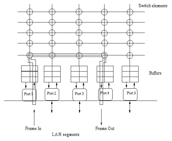
LAN exchanging is a manifestation of parcel exchanging utilized as a part of neighborhood. Exchanging advances are urgent to system outline, as they permit movement to be sent just where it is required as a rule, utilizing quick, equipment based systems. Layer 2 exchanging is exceptionally productive in light of the fact that there is no change to the information parcel, just to the edge epitome of the bundle, and just when the information bundle is passing through divergent media, (for example, from Ethernet to FDDI).
Layer 2 exchanging is utilized for workgroup integration and system division (separating crash spaces). This permits a compliment system plan with more system sections than customary 10baset imparted systems. Layer 2 exchanging has helped create new segments in the system framework.
The switch analyzes the bundle's end convention address and figures out if it knows how to forward the parcel or not. On the off chance that the switch does not know how to forward the bundle, it normally drops the parcel. In the event that it knows how to forward parcel, it changes the terminus physical location to that of the following jump switch and transmits the bundle.
The following bounce may be the objective or the following switch, which executes the same exchanging methodology. As the parcel travels through the internetwork, its physical location changes, yet its convention location stays same.
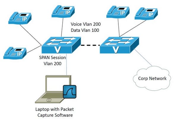
SPAN
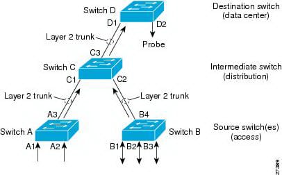
The Switched Port Analyzer (SPAN) characteristic (once in a while called port reflecting or port observing) chooses system movement for examination by a system analyzer. The system analyzer could be a Cisco Switch probe or other Remote Monitoring (RMON) test.
Cisco Nexus 1000v backings two sorts of SPAN:
- span (nearby SPAN) that can screen sources inside a host or VEM
- encapsulated remote SPAN (ERSPAN) that can send checked movement to an IP end of the line.
SPAN sources
The interfaces from which activity could be observed are called SPAN sources. These incorporate Ethernet, virtual Ethernet, port-channel, and VLAN. At the point when a VLAN is defined as a SPAN source, all backed interfaces in the VLAN are SPAN sources. Movement could be observed in the get course, the transmit heading, or both headings for Ethernet and virtual Ethernet source interfaces.
- receive source (Rx)-Traffic that enters the switch through this source port is duplicated to the SPAN end of the line port.
- transmit source (Tx)-Traffic that passageways the switch through this source port is duplicated to the SPAN objective port.
Source Ports
Cisco Nexus 1000v backings numerous source ports and various source VLANs. A source port has these qualities:
- can be port sort Ethernet, virtual Ethernet, port-channel, or VLAN.
- cannot be an end port.
- can be arranged to screen the bearing of movement -get, transmit, or both.
- source ports might be in the same or distinctive VLANs.
- for VLAN SPAN sources, all dynamic ports in the source VLAN are incorporated as source ports.
- must be on the same host.
Destination Ports
Every neighborhood SPAN session must have no less than one end of the line port (additionally called a checking port) that gets a duplicate of activity from the source ports. A goal port has these attributes:
- can be port sort Ethernet, virtual Ethernet, or a port channel.
- cannot be a source port.
- is rejected from the source list and is not checked on the off chance that it has a place with a source VLAN of any SPAN session.
- receives duplicates of transmitted and got movement for all observed source ports. In the event that a terminus port is oversubscribed, it can get to be congested. This clogging can influence activity sending on one or a greater amount of the source ports.
- must be on the same host (linecard) as the source port.
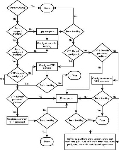
Troubleshooting the Span Problems
At the point when troubleshooting issues with SPAN, verify you have taken after these design rules and constraints:
- a most extreme aggregate of 64span and ERSPAN sessions might be arranged for every VSM.
- you can arrange a specific end port in standout SPAN session.
- you can't arrange a port as both a source and end port.
- when a SPAN session contains various transmit source ports, bundles that these ports get may be duplicated despite the fact that they are not transmitted on the ports. A few illustrations of this conduct on source ports are as takes after:
-traffic that comes about because of flooding
-broadcast and multicast activity
- for VLAN SPAN sessions with both get and transmit arranged, two parcels (one from get and one from transmit) are sent from the end of the line port if the bundles get exchanged on the same VLAN.
- after Vmotion:
-a session is halted if the source and end ports are differentiated
-a session resumes if the source and end
RSPAN
RSPAN expands SPAN by empowering remote observing of various switches over your system. The movement for every RSPAN session persisting to a client pointed out RSPAN VLAN that is devoted for that RSPAN session in all partaking switches. The SPAN activity from the sources is replicated onto the RSPAN VLAN through a reflector port and after that sent over trunk ports that is convey the RSPAN VLAN to any RSPAN objective sessions checking the RSPAN VLAN.
RSPAN Configuration
RSPAN sessions can coincide with SPAN sessions inside the breaking points depicted in the "Compass and RSPAN Session Limits" area.
- for RSPAN setup, you can appropriate the source ports and the end of the line ports crosswise over different switches in your system.
- a port can't serve as a RSPAN source port or RSPAN terminus port while assigned as a RSPAN reflector port.
- when you design a switch port as a reflector port, it is no more a typical switch port; just circled back movement passes through the reflector port.
- RSPAN does not help BPDU parcel checking or other Layer 2 switch conventions.
- the RSPAN VLAN is arranged just on trunk ports and not on access ports. To maintain a strategic distance from undesirable movement in RSPAN Vlans, verify that the VLAN remote-compass peculiarity is underpinned in all the taking part switches. Access ports on the RSPAN VLAN are noiselessly handicapped.
- RSPAN VLANs are incorporated as hotspots for port-based RSPAN sessions when source trunk ports have dynamic RSPAN VLANs. RSPAN VLANs can likewise be sources in SPAN sessions.
- you can design any VLAN as a RSPAN VLAN the length of these conditions are met:
-no access port is designed in the RSPAN VLAN.
-the same RSPAN VLAN is utilized for a RSPAN session as a part of every last one of switches.
-all taking an interest
Creating a RSPAN session
To begin with make a RSPAN VLAN that does not exist for the RSPAN session in any of the switches that will partake in RSPAN. With VTP empowered in the system, you can make the RSPAN VLAN in one switch, and VTP proliferates it to alternate switches in the VTP area for VLAN-Ids that are lower than 1005. See the "Making or Modifying an Ethernet VLAN" area for more data about making a RSPAN VLAN.
Use VTP pruning to get productive stream of RSPAN movement, or physically erase the RSPAN VLAN from all trunks that don't have to convey the RSPAN activity. In the wake of making the RSPAN VLAN, start in special EXEC mode, and take after these steps to begin a RSPAN source session and to detail the source (observed) ports and the terminus RSPAN VLAN.
Chassis Virtualization
As the Cloud Computing appropriation expands, virtualization is a key empowering influence, driving economies of scale and the capability to scale with equipment machines or ware fittings. Conveying versatility, adaptability and adaptability for changing movement volume, financially savvy on-interest methodology to decrease capital use and for public or private Clouds are some of the key aspects of chassis virtualization.
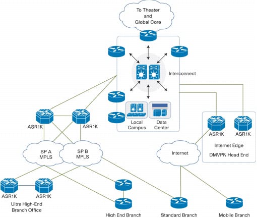
Aggregation technologies
The Cisco ASR 1000 Series Aggregation Services Routers present the Cisco IOS XE Software as their product structural planning. In light of the Cisco IOS Software, the Cisco IOS XE Software is a secluded working framework based on a Linux part on a Route Processor (RP), Embedded Services Processor (ESP), or SPA Interface Processor (SIP). The IOS daemon (IOSD) and different IOS XE procedures run on the Linux part, so there are a few sorts of accidents demonstrated in Table 1 on the Cisco ASR 1000 Series Aggregation Services Routers.
In the event that you experience a sudden reload of module, you must verify that the comfort yield, crash info document registry, and center dump record index are accessible for troubleshooting. Keeping in mind the end goal to focus the reason, the first step is to catch however much data about the issue as could reasonably be expected. This data is important to focus the reason for the problem. When a procedure crashes, you can discover a center dump document under the area indicated in Table 4. A center dump is a full duplicate of the memory picture of the methodology. It is prescribed that you spare the center dump records until troubleshooting is carried out. This is on account of a center dump incorporates significantly more data around an accident issue than a crash info record, and it is required for profound examination. On account of the Cisco ASR 1002 Router, since it doesn't have a hard disk: gadget, a center dump record is created under bootflash:core/
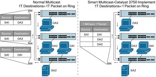
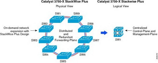
Stack Wise
Cisco Stack wise innovation gives an inventive new system to all in all using the abilities of a stack of switches. Individual switches brilliantly join to make a solitary exchanging unit with a 32-Gbps exchanging stack interconnect. Arrangement and directing data is imparted by every switch in the stack, making a solitary exchanging unit. Switches could be added to and erased from a working stack without influencing execution.
The switches are united into a solitary intelligent unit utilizing unique stack interconnect links that make a bidirectional shut circle way. This bidirectional way goes about as a switch fabric for all the joined switches. System topology and steering data is overhauled ceaselessly through the stack interconnect. All stack parts have full get to the stack interconnect data transmission. The stack is overseen as a solitary unit by an expert switch, which is chosen from one of the stack part switches.
Each one switch in the stack has the capacity to act as an expert or subordinate (part) in the progressive system. The expert switch is chosen and serves as the control community for the stack. Both the expert part switches go about as sending processors. Each one switch is relegated a number. Up to nine different switches could be joined together. The stack can have switches included and evacuated without influencing stack execution.
Single Management IP Address
The stack gets a solitary IP address as a piece of the introductory arrangement. After the stack IP location is made, the physical switches interfaced to it get to be a piece of the expert switch bunch. At the point when joined with a gathering, each one switch will utilize the stack IP address. At the point when another expert is chosen, it utilizes this IP location to keep connecting with the system.
Stack Creation and Modification
Stacks are made when individual switches are joined together with stacking links. At the point when the stack ports recognize electromechanical movement, each one port begins to transmit data about its switch. At the point when the complete set of switches is known, the stack chooses one of the parts to be the expert switch, which will be in charge of keeping up and overhauling setup records, directing data, and other stack data. The whole stack will have a solitary IP address that will be utilized by all the switches.
The main distinction between a layer 3 switch and switch is the way the head makes the physical usage. Likewise, customary switches use microchips to settle on sending choices, and the switch performs just equipment based parcel exchanging. Notwithstanding, some conventional switches can have other fittings works too in a portion of the higher-end models. Layer 3 switches might be set anyplace in the system on the grounds that they handle superior LAN activity and can cost-viably supplant switches. Layer 3 exchanging is all fittings based bundle sending, and all parcel sending is taken care of by equipment Asics. Layer 3 switches truly are the same practically than a customary switch and perform the same functions.the exchanging calculation is generally straightforward and is the same for the majority of the directed conventions: a host might want to send a parcel to a host on an alternate system. Having procured a switch's location by a few means, the source host sends the bundle straightforwardly to that switch's physical (MAC) address. The convention (system layer) location is that of the objective host.


Site Search:


