- Home
- Popular IT Certifications
- Frame Relay: Concept and Configuration
How to Configure , verify PPP and Basic concepts of Frame Relay
You can go through the basic configuration and verification of the Point to point protocol (PPP). In the same way, it helps to learn how to configure and verify a PPP along with the PAP and CHAP authentication, and PPoE. This will operate in the layer 2 technologies. Additionally, the frame relay is the very cost efficient data transmission telecommunication service for the intermittent traffic. In the below sections, the operation, point to point and multipoint of the frame relay are clearly explained in detail with circuits.
2.1 Configure and verify PPP
The PPP stands for the point to point protocol, which operates on the OSI model in the layer 2. The HDLC is the Cisco proprietary and it is the default encapsulation on the serial links if the user has all the Cisco devices, or else they need to be PPP configured. In that, there are 2 types of the authentication which can be used along with the PPP such as CHAP and PAP.
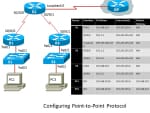
In the above diagram, 3 routers, loop back connection, 2 switches, and 2 PC's are used. If the packet tracer or real devices are used, then it is important to cable the network. Perform the basic router configuration, such as disable the DNS lookup, hostname, password for the console, the message of a day banner, EXEC password, VTY connections and along with the synchronous logging. Then configure the interfaces on the R1, R2 as well as R3 with an IP addresses from the addressing table. Make sure that an IP addressing is perfectly right and also the interfaces are active with the help of issuing the show brief command of IP interface. After that, test as well as configure the Ethernet interfaces on the PC1 and PC3 by simply pinging the gateway which is set as default. Now the entire devices are connected and start it by configuring the OSPF.
Configuring the PPP is rather so simple:
- configure terminal
- int s2/0
- encapsulation ppp
2.1.a Authentication (PAP, CHAP)
The PAP is the password authentication protocol. The passwords are sent in the form of plain text and there is no protection or encryption. Here no periodic checks at all. This PAP is only used by the point to point protocol to validate the users before permitting them access to the server resources. Most of the remote server's networking operating system will support PAP. It is the very basic 2 way process.
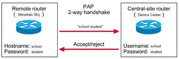
When the Point to point protocol authentication PAP command is used, then the password and username are sent as 1 LCP data package, instead of the server sending the login prompt and simply waiting for the response.
The CHAP is the challenge handshake authentication protocol. The passwords are encrypted. It sends periodic checks to assure the router is speaking to the same router. It is more secure than the PAP. It follows the 3 way exchange of the shared secret. Basically, the PAP will stop it works once the authentication is accomplished and it provides the way to a network with the vulnerable. But CHAP conducts the periodic challenges to ensure that a remote host has the valuable and valid password during the link establishment.
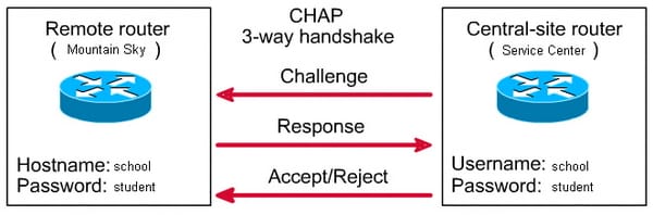
In this the central site router initiates the three way handshake and also sends the challenge message to the remote router. Then the remote router responds to the central site router by sending the username and password. Then again the central site router password and username in their local database for the possible match, if it matches with that, then it will accept the connection. If it doesn't match, it will reject it.
The configuration procedure of the CHAP is mostly straightforward. Imagine that 2 router which is connected as left and right as shown in the below figure across the network.
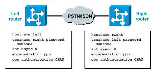
Issue the command of encapsulation PPP on the interface as the first step in the configuration. Then, enable the CHAP authentication use on both the routers by using the command of PPP authentication CHAP. Configure the password and username. To perform that, provide the username as "username" and the password as "password" command, here username is the peer hostname. It is essential to ensure that the passwords are same at the both ends and the router password and username are exactly identical, because it is case sensitive.
Step 1:
The call comes in from the 766-1 to 3640-1, which is the initial step in the configuration.
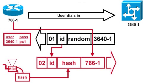
Step 2:
The CHAP challenge packet will build.
Step 3:
Receipt & MD5 processing of a challenge packet from a peer.
Step 4:
The CHAP response packet is sent to an authentication is built.
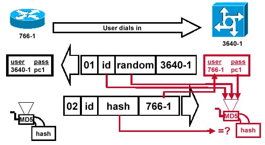
Verify:
From the below figure, it is possible to verify the CHAP configuration which is the most important step at most. In this the ID will help to find the real challenge packet and it is fed to the MD5 hash generator. Then the original challenge random number will fed to the ND5 hash generator. The 766-1 will search for the password from the local database or TACACS+server or RADIUS. Then the password will send to the MD5 hash generator. A hash value received in a response packet and compared with an MD% calculated hash value. The authentication process will succeed if a calculated hash value is equal.
2.1.b PPPoE(client side only)
The Ethernets are more causally called as PPPoE. It offers an emulated point to point link over the shared medium, especially the broadband aggregation network, which is found in the DSL service providers. The real fact is that, the scenario is to run the PPoE client on a user side, that connects to & acquire its configuration from a PPoE server at an ISP side. The ATM is run typically between the user's modem as well as DSLAM, though it can be transparent since the PPPoE client exists on the separate device.
In that, the client side configuration is relatively very simple. So that, create the dialer interface to manage a PPPoE connection and also tie that to the physical interface which offer the transport.
The dialer interface of the PPPoE:
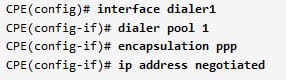
Here, the line " ip address negotiated" is the one which instructs the client to use the IP address offered by a PPPoE server.
2.2 Explain Frame relay
The frame relay is the standardized WAN technology, which specifies the logical and physical link layers of the digital telecommunication channels with the help of the packet switching methodology. It is designed for the cost efficient data transmission for the intermittent traffic in between the LAN and between the end points in the WAN. This frame relay adds data in the variable size unit called to an end point, that speeds the overall data transmission. This frame relay is provided by the number of the service providers such as AT & T. It is offered on the full T carrier system or functional T-1. The frame relay provides and complements the mid range service in between the ISDN, that offers the bandwidth at the 128 kbps and ATM, which runs in the same fashion to the frame relay but at the speeds from the 622.080 Mbps or 155.520 Mbps.
The frame relay is merely based on an older X.25 technology of packet switching that was designed for transferring the analog data like voice conversation. It is most often helps to connect the LANs with the major backbones and on the public WANs as well as in the private network environments with a leased line over the T-1 lines. It gives the dedicated and responsible connection during the period of transmission. Although, under some circumstances, the frame relay is used for the video and voice transmission.
It relays the packets at a data link layer of the OSI- open system interconnection model instead of the network layer. The frame can also incorporate the packets from the various protocols, including X.25 and Ethernet. It can be huge as a thousand bytes/ more and varies in size.
2.2.a Operations
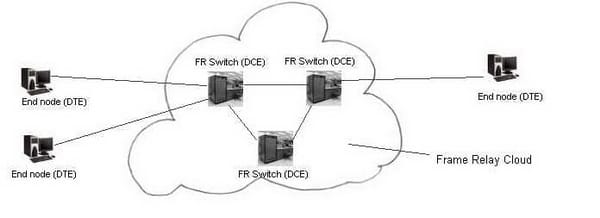
The frame relay is considered as the FR which consists of the customer nodes and FR switches. The frame relay switches will act as as the DCE and a customer equipment will work as the DTE. The virtual circuit is accomplished in between the DTE as well as the corresponding DCE. The virtual circuit is the one which identified by the Data link connection identifier - DLCI number. This DLCI has the local significance. It implies that the provided physical channel, there may not be 2 DLCI which are similar.
The frame relay is the packet switched network as well as it may compare with the X.25 network. However, both the X.25 and frame relay uses the similar basic HDLC protocol, there are many differences in between those two. The basic frame protocol, which is used in the frame relay is HDLC and the typical speed is higher than the X.25. The LAN connectivity for faster file transfers and interactive sessions are suitable for the frame relay and the protocol overhead as well as protocol complexity is comparatively lower than the X.25. The frame relay is implemented widely nowadays, which does not support the error correction of the node to node.
2.2.b Point-to-Point
The point to point frame relay is the easiest one to configure. On the networks of the frame relay, the single VC originates at the local end and also terminate at a remote end. The subnet address is normally designated to the each connection of the point to point. Hence, only 1 DLCI has to configure with the point to point in the subinterface cases. For example, take the VC's local referenced DLCI at the hub router R3 is 304 & spoke routers as R4 is 403. The subnet address of 192.168.1.0/30 is allocated to that point to point network. Normally, the 30 bit subnet masks are used for the point to point connections to save the address space.
In that, the destination is identified as well as configured with a frame relay interface DLCI command at the beginning of the interface configuration mode. When it's configured, the command associates the chosen point to point with the DLCI. This command allows the user to choose the frame relay encapsulation type which has to be used on the particular VC. The command will be executed by without indicating the type of the frame relay encapsulation to be used.
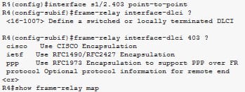
Serial1/2.403 (up): point-to-point dlci, dlci 403(0xC9,0x3090), broadcast
status defined, active
R4#
( The output of the point to point frame relay as shown above)
While creating the frame relay, it is better practice to assign the subinterface number of the frame relay that the mirror a PVC frame relay DLCI value to that subinterface. In this case, there is no need to use the command of the frame relay map to perform the static address mapping. It most often assumes that an end point of a point to point connection resides automatically on a same subnet at the starting point.
2.2.c Multipoint
By default, the physical interfaces are the multipoint interfaces on the Cisco router especially. When the multipoint Subinterfaces are created in the physical interface, then it is essential to assign DLCI specific to a multipoint subinterface. As default, the IOS software on the Cisco allocates all the unassigned DLCI are advertised by a fire, we relay switch to a router physical interface.
When the multipoint subinterfaces are created on the physical interface, then the DLCI of the virtual circuit is always assigned to a physical interface until it's specifically allocated to a subinterface with the help of the frame relay map protocol or frame relay interface DICI.
By learning the above things clearly, the configuration and verification of the PPP along with the CHAP and PAP authentication, PPPoE- client side only. This protocol and authentication techniques are widely used in the Cisco routers. The frame relay is the other wonderful topic explained with, perfect example and configuration. From that, it is very easy to understand the operations, multipoint and point to point types of the frame relay. This will help to gain greater knowledge on the frame relay.


Site Search:


