- Home
- Popular IT Certifications
- OSPF Problems: Troubleshooting Tips
How to troubleshoot and resolve OSPF problems
OSPF is important part when it comes to networking. So, those people who are willing to give future in this field are supposed to know this technique. It stands for the "open shortest paths first". Hence it allows the user to find the shorts path which he can use first.
It is a late section into the Internet inner part routing scene. OSPF Version 2 is reported in RFC 1583 (an extensive report that I discover exceptionally hard to peruse). Endorsed by the IETF, it is planned to turn into Internet's favored inside routing protocol. OSPF is a connection state routing protocol with a complex set of alternatives and peculiarities. Not these peculiarities are accessible on all usage, however some of its points of interest are:
- Adaptability. OSPF is particularly intended to work with bigger systems. It doesn't force a bounce check limitation and licenses its area to be subdivided for less demanding administration.
- Full sub-netting backing. OSPF can completely help sub netting, including VLSM and non-coterminous subnets.
- Hello packets. OSPF utilizes little "hi" bundles to check join operation without exchanging substantial tables. In steady systems, substantial upgrades happen just once at regular intervals.
- TOS routing. OSPF can course bundles by diverse standard focused around their Type of Service (TOS) field. For instance, document exchanges could be directed over a satellite connection while terminal I/O could maintain a strategic distance from such high defers. This obliges agreeable applications on the end frameworks. Labeled courses. Courses could be labeled with subjective qualities, maneuvering interoperation with EGPS, which can label OSPF courses with AS numbers. OSPF has a few impediments also. Boss among them are its unpredictability and its requests on memory and processing. In spite of the fact that connection state protocols are not hard to comprehend, OSPF tangles the picture with a lot of alternatives and gimmicks. OSPF partitions its routing space into regions. Region 0, the spine, is needed. These partitions inside routing into two levels. In the event that movement must go between two territories, the bundles are initially steered to the spine. This may cause non-ideal courses, since inter area routing is not done until the packet achieves the spine. Once there, it is steered to the terminus region, which is then in charge of last conveyance. This layering licenses locations to be combined by territory, lessening the extent of the connection state databases. Little systems can work with a solitary OSPF territory, which must be zone 0.
OSPF partitions systems into a few classes, including point-to-point, multi-access, and non-telecast multi-access. A serial connection joining two switches together would be a point-to-point connection, while an Ethernet or Token Ring fragment would be a multi-access join. A Frame Relay or X.25 cloud would be delegated non-telecast multi-access. About an N^2 blast in the quantity of connections. Rather, the DR deals with all the connection state ads for the Ethernet. Selecting the DR requires a decision methodology, amid which a Backup Designated Router (BDR) is additionally chosen. OSPF gives a necessity gimmick to help the system architect impact the decision of DR and BDR, Multi-access systems (like Ethernet) utilize an assigned switch (DR) to evade the issue of every switch structuring a connection with each other switch on an Ethernet, bringing however in practice this is troublesome. Connection layer multicasting is additionally utilized, if accessible, to stay away from telecasts and better target routing upgrades. Non-show multi-access systems (like X.25) additionally utilize the assigned switch idea, however since shows (and apparently multicasts) are not underpinned, the character of neighboring switches must be pointed out physically. A DR on such a system without a complete rundown of neighbors will result in a loss of integration, despite the fact that the system is overall useful. In the event that conceivable, I suggest arranging such systems as an accumulation of point-to-point joins, essentially to stay away from the intricacies of DR race. OSPF's essential method for checking proceeding with operation of the system is by means of its Hello Protocol. Each OSPF speaker sends little hi bundles out each of its interfaces like clockwork. It is through receipt of these bundles that OSPF neighbors at first learn of one another's existence. Hi bundles are not sent or recorded in the OSPF database, yet in the event that none are received from a specific neighbor for forty seconds, that neighbor is checked. LSAS are then produced stamping connections through a down switch as down. The welcome clock qualities might be arranged; however they must be consistent over all switches on a system portion. Connection state notices additionally age. The beginning switch advertises a LSA after it has stayed unaltered for thirty minutes. On the off chance that a LSA ages to more than an hour, it is flushed from the databases. These clock qualities are called structural constants by the RFC.
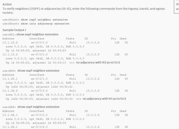
Verify neighbor adjacencies
Here, Example Output 1 from the entrance, travel, and departure switches demonstrates that R1 and R3 are not settled OSPF neighbors. Considering that the two interfaces so-0/0/2.0 (R1 and R3) are designed with indistinguishable IP addresses, you would expect this. The OSPF protocol courses IP bundles built singularly in light of the goal IP location contained in the IP parcel header. Thusly, indistinguishable IP addresses in the self-sufficient framework (AS) result in neighbors not making.
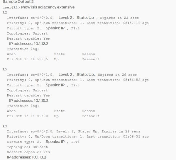
Specimen Output 2 from the entrance, travel, and departure switches demonstrates that R1 and R3 have made an IS-IS contiguousness notwithstanding the indistinguishable IP locations designed on interfaces so-0/0/2.0 on R1 and R3. The IS-IS protocol carries on uniquely in contrast to the OSPF protocol on the grounds that it doesn't depend on IP to secure a contiguousness. Then again, if the LSP is not up, it is still helpful to check the IP subnet tending to on the off chance that there is a slip-up in that layer. Rectifying the tending to blunder may bring the LSP move down.
Verify hello and dead timers
The routing protocol clocks are the exuberant hood of a routing protocol. Through the utilization of clocks, the routing protocol can keep up a stable neighbor relationship and guarantee courses are spread effectively. Clocks in OSPF are similar to the clocks in EIGRP; you have a Hello clock and a Dead clock. The welcome clock is the interim at which the routing procedure sends hi parcels to its straightforwardly joined neighbor with a TTL of 1 and the dead clock is the interim at which a switch will announce a neighbor down if hi bundles are not gotten from that neighbor in the time pointed out by the dead-interim. The OSPF clocks on a Cisco switch rely on upon what time of interface they are utilized on.
Naturally the clocks on a show system which incorporate Ethernet, point-to-point and point-to-multipoint are 10 seconds hi and 40 seconds dead. The clocks on a non-show system are 30 seconds hi 120 seconds dead. The Hello and Dead clocks must match to structure a neighbor relationship in OSPF. Likewise when consolidating distinctive OSPF system sorts, for example, point-to-point and point-to-multipoint you must alter the clocks to match as point-to-multipoint is 30/120 naturally and point-to-point is 10/40 of course. The dead-clock is normally four times the measure of the welcome clock to give time for parcel misfortune/drops because of system issues and/or nature of administration approaches.
In this lab you will design the OSPF hi and dead on the point to point connect in the middle of R2 and R3 to 1 second hi and 4 second dead. The charges to design the clocks statically are executed under interface arrangement mode and is carried out on a for every interface premise.
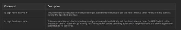
To arrange the welcome clock, you'd utilize the IP OSPF hi interim # while # is a number somewhere around 1 and 65535 seconds. To arrange the dead clock you'll utilize the IP OSPF dead-interim # while # is a number somewhere around 1 and 65535 seconds.
Here is the command for it;
Verify OSPF area
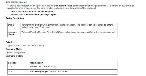
Pointing out validation for a range sets the verification to Type 1 (basic secret word) as indicated in RFC 1247. On the off chance that this command is excluded in the setup record, validation of Type 0 (no confirmation) is accepted. The verification sort must be the same for all switches and access servers in a range. The validation secret key for all OSPF switches on a system must be the same on the off chance that they are to speak with one another by means of OSPF. Utilize the IP OSPF validation key interface command to indicate this secret key. On the off chance that you empower Md5 confirmation with the message-digest catchphrase, you must arrange a secret word with the IP OSPF message-overview key interface command. To uproot the validation detail for a zone, utilize the no manifestation of this charge with the confirmation magic word.
Verify interface MTU
MTU confuses are the essential reason an OSPF contiguousness gets to be stuck in the EXSTART state. After welcomes are traded and the switches get to be neighbors, every OSPF speaker publicizes the IP MTU of its nearby interface in a Data Base Description (DBD) LSA. . On the other hand, when you attempt to associate two OSPF switches with diverse system working frameworks, things begin to go into disrepair reasonably quickly. If you're acquainted with Cisco IOS on switches, you'll realize that there are two interface level charges accessible: "MTU" and 'IP MTU'. Ivan Pepelnjak calls this first MTU the 'fittings MTU', and I'll embrace that term here. All MTU's are measured in bytes. The point of the 'equipment MTU' is to guarantee that physical interface can deal with the full datagram when layer-2 surrounding overhead is added to the greatest IP parcel size. The 'IP MTU' is the most extreme measured IP parcel that could be transmitted out an interface. The switch will need to part an IP bundle before transmission on the off chance that it surpasses the 'IP MTU'.
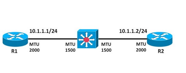
On Cisco IOS by the "MTU" and 'IP MTU' are situated to both set to1500 bytes naturally, which truly befuddled me. By what means would you be able to have an IP MTU of 1500 bytes and after that include a 18-byte Ethernet header, yet at the same time keep your aggregate casing size under the 1500 byte 'fittings mute'?many systems have OSPF neighbors which are associated through a Layer 2 exchanged system, or transport system, included L2vpn administration or a SDH/SONET system. These vehicle systems can have distinctive MTU settings than the switches running OSPF. The MTU setting ought to be right on all switches, reflecting the genuine MTU, there are regularly mix-ups and they can go unnoticed. Here's an illustration system, with two switches R1 and R2 running OSPF and they are joined through a Layer 2 switch.
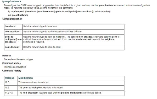
Verify network types
At the point when building out an OSPF system you must mull over of the web system sorts. This is subject to the layer 2 engineering utilized, for example, Ethernet, point-to-point T1 circuit, edge hand-off and even casing transfer with no telecast. There are five diverse configurable OSPF system sorts on a Cisco switch, telecast, non-show, point-to-point, point-to-multipoint and point-to-multipoint non-telecast. As a system build in the field working with OSPF you must know the distinctions in the OSPF system sorts and which sorts are good with each other. A few sorts will work with one another yet you need to alter the welcome/dead clocks.
Verify neighbor states
At the point when OSPF nearness is framed, a switch experiences a few state changes before it gets to be completely neighboring with its neighbor. Those states are characterized in the OSPF RFC 2328 leavingcisco.com, area 10.1. The states are Down, Attempt, Init, 2-Way, Exstart, Exchange, Loading, and Full.
Review OSPF topology table
Topology table is a table that could be characterized as a guide of any system topology, which contains all the conceivable routing information and all the ways, great or awful yet all the paths (routes/systems). Be that as it may Topology table is not utilized by a few protocols. On account of EIGRP and OSPF .They both utilize it!! Topology table is utilized to discover the best paths, and each protocol run their calculations, onteh Topology table, however the topology table is never utilized for the official conclusion it's simply used to fabricate the best ways and courses as indicated by particular protocols, whichever the calculation the y utilize!
Hence OSPF has many perks under its sleeves. It allows the users to gather data more quickly and plays an important role when it comes to networking. So through this article, you can gather all information about it.


Site Search:


