- Home
- Popular IT Certifications
- RSTP, PVSTP, Etherchannels, PVSTP Operation
Describe enhanced switching technologies: RSTP, PVSTP, Ether channels and the process of configuring and verifying PVSTP operation
Most business systems today utilize switches to interface machines, printers and servers inside a building or facilities. A switch serves as a controller, empowering arranged gadgets to converse with one another proficiently. Through data offering and asset designation, switches spare organizations cash and build worker benefit. Here are the important terminologies related to switching;
RSTP
The execution of an Ethernet system might be contrarily affected by the arrangement of an information circle in the system topology. An information circle exists when two or more hubs on a system can transmit information to one another over more than one information way. The issue that information circles posture is that information parcels can get to be discovered in rehashing cycles, alluded to as telecast storms that unnecessarily devour system transfer speed and can essentially diminish system performance. RSTP keeps information circles from structuring by guaranteeing that stand out way exists between the end hubs in your system. Where various ways exist, this protocol puts the additional ways in a standby or blocking mode, leaving stand out fundamental dynamic way.
RSTP can likewise initiate a repetitive way if the fundamental way goes down. So not just do these protocols prepare for various connections in the middle of sections and the danger of telecast storms, yet they can additionally keep up system network by actuating a reinforcement repetitive way on the off chance that a primary connection fails. When a change is made to the system topology, for example, the expansion of another scaffold, a spreading over tree protocol must figure out if there are excess ways that must be hindered to avert information circles, or initiated to keep up interchanges between the different system portions. This is the procedure of convergence. RSTP can finish a joining in seconds, thus enormously lessens the conceivable effect the methodology can have on your system.
At this point, just RSTP is accessible on the AT-8000/8poe Fast Ethernet switch. TheRSTP execution conforms to the IEEE 802.1w standard. The accompanying subsections give an essential outline on how RSTP works and characterize the diverse parameters that you can modify.
Enabling and Disabling the RSTP:
To empower or impair RSTP, perform the accompanying methodology:
- From the Main Menu, sort B to choose Basic Switch Configuration.
- From the Basic Switch Configuration Menu, sort S to choose Rapid Spanning Tree Configuration.
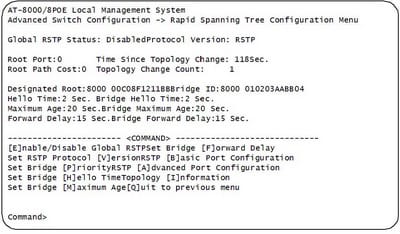
TheRSTP menu permits you to arrange RSTP and in addition to view the current settings and contains the accompanying things of data in the center part:
Root Port It is the dynamic port on the switch that is corresponding with the root span. On the off chance that the switch is the root span for the LAN, then there is no root port and the root port parameter will be 0.
Time since Topology Change The time in seconds since the last topology change occurred. At the point when RSTP discovers a change to the LAN's topology or when the switch is rebooted, this parameter is reset to 0 seconds and starts augmenting until the following topology change are discovered.
Topology Change Count A whole number that reflects the quantity of times RSTP has discovered a topology change on the LAN since the switch was at first controlled on or rebooted.
PVSTP
For every VLAN Spanning Tree (PVST) keeps up a traversing tree case for every VLAN designed in the system. It utilizes ISL Trunking and permits a VLAN trunk to be sending for a few VLANS while hindering for different VLANS. Since PVST treats every VLAN as a different system, it can load offset movement (at layer-2) by sending a few VLANS on one trunk and different VLANS on an alternate trunk without bringing on a Spanning Tree loop.so what happens when you plug two non-oversaw switches together utilizing two hybrids and a PC's on both switches. After a brief time of time you will perceive that the LED's on those switches will be blazing greatly quickly and system execution will be moderate as a turtle creeping on the web from Miami to New York.
The purpose behind this is known as a telecast storm. A Broadcast storm is the place a switch advances a telecast out all ports aside from the port the show was gotten on and when you have two connections between switches the show about-faces and forward until the connections get overpowered with telecast activity to the point where the system is slower than a 56k modem.
So how would you settle this issue? It's called crossing tree. Crossing tree is a protocol that catches and wipe out layer two circles in the exchanging topology to counteract telecast storms. So when you have two connections between two switches, one connection gets blocked totally; accordingly adequately slaughtering the potential for a show storm on a layer two systems administration circle additionally murders the value of a repetitive link. What is the purpose of two connections between two switches if you can utilize a solitary connection? By what means would you be able to alter that to utilize both connections to forward activity? As beforehand examined in a lab you can utilize an innovation called Ether channel which packages different connections into a solitary legitimate connection and is prepared all things considered. At the point when spreading over tree looks into the system it takes a gander at a Port-Channel interface as a solitary interface and not all the physical interfaces bound in that channel bunch.
An alternate fix to utilize various connections and not utilize an ether-channel is to load parity activity over the two connections utilizing distinctive VLANS. Join one advances movement for the odd VLAN's and squares even VLAN activity and connection two advances even vlan movement and pieces odd vlan movement. This will be examined in Lab 4-15 - Configuring Multiple Spanning Tree Protocol.
The first Spanning Tree protocol (802.1d) is truly antiquated by today's measures and just chipped away at a solitary VLAN or a solitary switch that does not help VLANS. Cisco saw the requirement for Spanning Tree on all VLAN's and make the exclusive PVST and PVST protocols which empower spreading over tree on a for every vlan case. So for this situation each and every vlan on each one switch has its own particular STP methodology racing to identify and dispense with circles in a layer two exchanging network. Spanning tree utilizes BPDU (Bridge protocol information units) to transmit data between switches in regards to switches expense to the root or amid root decision. Root is chosen by the most minimal MAC address if the convent is left at the default 32768, or by the least necessity
Ether channels
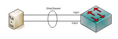
Ether channel is a port connection collection innovation or port-channel structural planning utilized principally on Cisco switches. It permits gathering of a few physical Ethernet connections to make one coherent Ethernet join with the end goal of giving flaw tolerance and fast connections between switches, switches and servers. An Ether channel could be made from somewhere around two and eight dynamic Fast, Gigabit or 10-Gigabit Ethernet ports, with an extra one to eight latent (failover) ports which get to be dynamic as the other dynamic ports come up short. Ether channel is fundamentally utilized within the spine system, however can likewise be utilized to join end client machines.
Ether channel engineering was designed by Kaplan in the early 1990s. They were later procured by Cisco Systems in 1994. In 2000 the IEEE passed 802.3ad which is an open standard variant of Etherchannel.Using an Ether channel has various focal points, and likely the most attractive perspective is the transfer speed. Utilizing the most extreme of 8 dynamic ports an aggregate data transfer capacity of 800 Mbit/s, 8 Gbit/s or 80 Gbit/s is conceivable relying upon port pace. This accepts there is an activity mixture, as those velocities don't have any significant bearing to a solitary application just. It could be utilized with Ethernet running on bent pair wiring, single-mode and multimode fiber. Since Ether channel exploits existing wiring it makes it exceptionally adaptable. It could be utilized at all levels of the system to make higher data transfer capacity connects as the activity needs of the system build. All Cisco switches can help Ether channel.
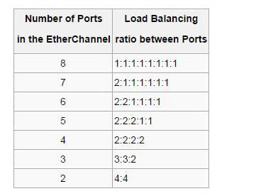
At the point when an Ether channel is designed all connectors that are a piece of the channel have the same Layer 2 (MAC) address. This makes the Ether channel transparent to system applications and clients on the grounds that they just see the one consistent association; they have no learning of the individual connections. Ether channel totals the movement over all the accessible dynamic ports in the channel. The port is chosen utilizing a Cisco-exclusive hash calculation, in light of source or objective MAC addresses, IP addresses or TCP and UDP port numbers. The hash capacity gives a number somewhere around 0 and 7, and the accompanying table demonstrates how the 8 numbers are circulated among the 2 to 8 physical ports. In the theory of true irregular hash calculation, 2, 4 or 8 ports designs lead to reasonable burden adjusting, while different arrangements lead to out of line burden adjusting.
Describe root bridge election
Utilize the extension necessity to control which scaffold is chosen as the root extension furthermore to control which scaffold is chosen the root span when the beginning root extension comes up short.The root span for each one traversing tree protocol occurrence is controlled by the extension ID. The scaffold ID comprises of a configurable extension necessity and the MAC location of the extension. The scaffold with the most minimal extension ID is chosen as the root span. On the off chance that the extension necessities are equivalent or if the scaffold necessity is not arranged, the extension with the least MAC location is chosen the root span. The extension necessity can likewise be utilized to figure out which scaffold turns into the assigned scaffold for a LAN fragment. On the off chance that two extensions have the same way cost to the root connect the scaffold with the most minimal extension ID turns into the assigned scaffold.
Consider a specimen situation in which a double client edge (CE) switch is associated with two other supplier edge (PE) switches, which work as the VPLS PE switches, with MTSP empowered on all these switches, and with the CE switch working as the root span. Coordinated Routing and Bridging (IRB) interface is designed for the VPLS steering cases on the switches. In such a system, the MAC addresses that are adapted in the VPLS space constantly move between the LSI or virtual shaft (VT) interfaces and the VPLS interfaces on both the PE switches. To dodge the nonstop development of the MAC addresses, you must arrange root security by including the no-root-port proclamation at the [edit steering cases directing occurrence name protocols MSTP interface-name] pecking order level and design the extension necessity as zero by including the scaffold necessity 0 announcement at the [edit steering occurrences directing occasion name protocols MSTP] progression level on the PE switches. This design on the PE switches is obliged to keep the CE-side confronting interfaces from turning into the course connect.
Spanning tree mode
Crossing Tree Protocol (STP) is a Layer 2 protocol that runs on extensions and switches. The particular for STP is IEEE 802.1d. The principle motivation behind STP is to guarantee that you don't make circles when you have excess ways in your system. Circles are dangerous to a system.
STP runs on extensions and switches that are 802.1d-agreeable. There are distinctive kinds of STP, however 802.1d is the most well-known and broadly executed. You actualize STP on extensions and switches so as to avoid circles in the system. Use STP in circumstances where you need excess connections, however not circles. Excess connections are as critical as reinforcements on account of a failover in a system. A disappointment of your essential actuates the reinforcement interfaces with the goal that clients can keep on using the system. Without STP on the scaffolds and switches, such a disappointment can bring about a circle. In the event that two joined switches run diverse kinds of STP, they require distinctive timings to merge. At the point when diverse flavors are utilized as a part of the switches, it makes timing issues in the middle of Blocking and Forwarding states. Accordingly, it is prescribed to utilize the same kinds of STP.
Hence by reading this all, one can know how important switches are and how beneficial it is to learn about them since they can add some great amount to knowledge to one's mind.


Site Search:


