- Home
- Popular IT Certifications
- Spanning Tree and LAN Switching Technologies
How to Configure and verify spanning tree and LAN switching technologies
The STP runs on switches and bridges which are 802.1D compliant. There are different types of STP, but the 802.1D is the most famous one and is widely used. STP is implemented on switches and bridges to avoid network loops. STP is used in situation where redundant links are required instead of loops. Redundant links hold equal importance as that of backup system in a network.
Configure and Verify spanning tree:
1. MST:
MST- more commonly known as the multiple spanning tree is the IEEE 802.1 standard, it allows you to assign more than one VLAN to the spanning tree instance MST isn't the spanning tree default mode; RPVST+ is the default mode. MST requests with the same revision number, name and VLAN to form MST region. MST area is displayed as the single bridge to configurations of spanning tree outside thee MST region. MST falls on to STP after receiving 802.1D message through a neighboring switch. MST maps several VLANs into the spanning tree instance, with very instance having a unique STP topology, free o other instances of spanning tree. The architecture of MST allows numerous forwarding pathways for data traffic, enabling the load balancing and minimizing the number of spanning tree instances needed to support a high number of VLANs. MST enhances the fault tolerance performance of a network as failure in one case does not have an impact on the other forwarding paths
MST improves the fault tolerance of the network because a failure in one instance (forwarding path) does not affect other instances (forwarding paths). MST provides fast convergence through plain handshaking as every MST instances utilized the IEEE 802 standard that removes the 802.1D forwarding
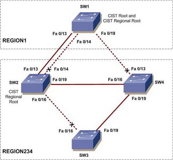
MST Regions
For switches to be able to perform in MST instances, it is important to consistently configure switches with similar MST configuration data. A range of interconnected switches which has similar MST configuration is the MST region. The MST region is an associated group of MST bridges with similar MST configuration. The MST configuration handles the MST region where each switch belongs. The configuration consists of the name of revision number, region and MST VLAN. A region can include more than one member with similar MST configuration. Each member should be capable of controlling 802.1w BPDUs. There is no limit of MST regions within a network.
MST BPDUs
Every region of MST includes only a single BPDU, tat BPDU includes an M-record for every MST within a region. As the MST BPDU carries data and information regarding all instances, the number of BPDUs required to be processed for MSTIs support are significantly reduced.
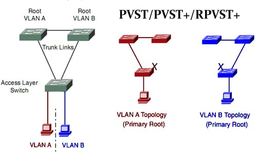
2. PVST+
PVST controls the spanning tree instance for every VLAN that is configured in a network. ISL trunking is used which allows the trunk to forward for VLANS when blocking for the other VLANs. As the PVST works with each VLAN as separated network, it has the capability to load balance the traffic forwarding some VLAN on single trunk and other VLANS on another without affecting the STP loop.
Switch priority:
Port priority:
The spanning tree uses the feature of port priority in case of a loop occurrence while selecting a port for putting into the state of forwarding. You are able to assign larger priority values to the ports which you wish to be selected first and the lower priority values which you want to be selected in the last. If all the spanning tree ports include the same priority value, the port results in having the lowest interface no. in state of forwarding and blocks the rest of the interfaces.
Path Cost:
The default value of spanning tree path is derived through the media speed of a port channel or port running. In case of loop, cost is used by spanning tree while selecting a port to be placed in the forwarding state. You are able to assign low cost values to ports that you wish to be selected first and high cost values to the ones you want to be selected in the last. If all the interfaces will have the same values of cost, the spanning tree will put the port with smallest interface number in the state of forwarding, blocking the rest of the interfaces.
Configuring Spanning-Tree Timers
Configuring Hello Time-
You are able to configure interval between generations of messages by root switch using the changing hello time. While using this command, care should be taken. In most situations it is recommended to use the VLAN spanning tree ID and VLAN spanning tree root secondary configuration command to change the help time. Following are the steps that should be followed in the EXEC privileged mode, the procedure is only optional.
- Use no VLAN spanning tree id hello time configuration command for returning to the default setting
Variable Description
Hello timer- This feature controls the times a switch spreads hello message to the other switches.
Forward timer- This feature controls how long each learning and listening state lasts before the beginning of STP port forwarding.
Maximum age timer- This feature controls the amount of time a switch will store the information of a protocol received on STP port.
PORT FAST:
The function of port fast is to immediately retrieve the port configured as trunk or access port to the state of forwarding, blocking state, and listening, bypassing and learning states. Port fast can be used on ports that are connected to s ingle server or workstation. These devices are then immediately allowed to connect with a network, instead of waiting for the convergence of spanning tree. Ports that are connected to a single server or workstation should not have BPDUs (bridge protocol data units). A port that is port fast enabled will go through the usual cycle of STP changes once the switch is restarted.
BPDU Guard:
This feature can be enabled globally on the switch or enabled per interface; however, BPDU guard operates with certain differences. You can enable on port fast ports the BPDU guard at global level through spanning tree BPDUgaurdportfast default command. Spanning tree will shut down the ports that are working in an operational state of port fast. Ports enabled with port fast, in the right configuration will not receive BPDUs. In case of receiving a BPDU on ports enabled with port fast signals about an invalid configuration, like unauthorized device being connected, and then the BPDU guard will put the port in err disable state. BPDU guard can be enabled on the interface level by using the STP BPDU guard enables interface command, avoiding the port fast enabling. A port that receives BPDU will be put in err disable state. The BPDU guard feature will give a secure response to the invalid configuration because you should manually allow the port to be back in service. You should use the BPDU feature avoid access port in a service provider network from interfering in the spanning tree. MSTP and PVST are being run by your switch; BPDU guard can be enabled for the whole interface and switch. MSTP feature can only work when you have ESI installed on your port.
BPDU Filtering
This feature can also be globally enabled on a port or switch, however, BPDU filter operates with certain differences. BPDU filter can be enabled at global level on port fast ports with spanning tree bpdufilterportfast default command. This command ensures that ports operating in port fast state will not send or receiving BPDUs. The interface however still sends at link up some BPDUs before the switch starts to filter out the outbound BPDUs. BPDU filtering should be globally enabled on the switch as to prevent the hosts connected with these ports from receiving the BPDUs. In case of BPDU have being received on the port that is port fast enabled, the port will lose its port fast enabled state, and the filtering will be disabled. On the interface level, BPDU filtering can be enabled on any port or interface without port fast feature being enabled, by using the spanning tree BPDU filter.
Root Guard:
Enabled root guard on the port is applicable to all VLANs to which the port belongs. It is recommended to not enable this feature on port that is to be used by Uplinkfast feature. In Uplink fast, the backup port will replace the root port in the failure situation. However, in case the root guard is enabled, the backup ports by uplink fast will be placed in the state of root inconsistent (blocked) and will be prevented from reaching to the forwarding state. This feature can be enabled in case your switch is MSTP or PVST running.
Loop Guard:
Loop guard feature can be used to avoid the root or alternate ports from becoming the designated ports due to the failure which leads to unidirectional link. This feature works most effectively when configured on the complete switched network. Loop guard will only operate on the ports that are known to be point to point by ST. You are also able to enable loop guard feature in case your switch is MSTP and PVST running. MSTP feature can only work when you have ESI installed on your port. It is by default globally disabled.
2. LAN Switching technologies:
SPAN
The session of local SPAN is source port associated with more than one destination. Local SPAN is configured on a single port/switch. There are no separate destination session and source in local SPAN. It does not copy the locally source VLAN RSPAN traffic from source trunk ports carrying the RSPAN VLANs. Also, it will not copy RSPAN GRE encapsulated traffic locally sourced from the source ports. Each of the SPAN session can either have VLAN or port as sources. Prior to SPAN enabling, carefully analyze the traffic rates of SPAN source, and judge the implications and performances with possible points of oversubscriptions, including these:
- Fabric channel
- SPAN destination
- DFC/PFC
- Replication engine/rewrite
To prevent disrupting traffic, it is important to not oversubscribe in SPAN topology any of the mentioned points. Other than that, some performance and oversubscription considerations are:
- SPAN will internally double traffic
- SPAN will double the load of forwarding engine
- SPAN will add to the processed traffic through switch fabric.
RSPAN:
This feature supports the source VLANS, destinations and source ports on various switches, which allows remote monitoring of numerous switches working across the network. RSPAN will use VLAN layer 2 for carrying the traffic of SPAN between switches.
RSPAN includes the RSPAN VLAN, RSPAN destination and RSPAN source session. This allows you to separately configure the RSPAN destination sessions and source sessions on multiple switches. For configuring the RSPAN source session of single switch, you can link a set of VLANs and source ports with RSPAN VLAN. For RSPAN destination configuration session on the other switch, you can link the destinations with RSPAN VLAN. The RSPAN session traffic is carried by layer 2 as nonroutable traffic over the user specified RSPAN VLAN which is dedicated for the specific RSPAN session in all of the participating switches. The participating switches should be trunk connected at the layer 2. It does not copy the locally source VLAN RSPAN traffic from source trunk ports carrying the RSPAN VLANs. Also, it will not copy RSPAN GRE encapsulated traffic locally sourced from the source ports. Each of the SPAN session can either have VLAN or port as sources. The RSPAN source session will copy the traffic from source VLAN or source ports and transfers traffic to the RSPAN destination session.
RSPAN Restrictions and Guidelines:
Following are the restrictions and guidelines of RSPAN:
- Every participating switch should be connected by the trunks at layer 2
- Network devices which support VLAN RSPAN can also be an intermediate RSPAN device
- Network puts no limit on RSPAN VLAN number that the network carries.
- The intermediate network device may put limits of the RSPAN VLAN numbers that are not supported.


Site Search:


