- Home
- Popular IT Certifications
- How to Configure and Verify GRE
How to Configure and verify GRE
The virtual private network (VPN) extends the private network across the public network such as the internet. Some of the virtual networks will not use an encryption to protect the data privacy. The GRE stands for generic routing encapsulation. It is the protocol which encapsulates the packet in order to route the other protocols over the IP networks. The GRE is defined by the RFC 2784. The GRE was developed as the tunneling tool which is meant to carry any of the OSI layer 3 protocol over the IP network. Lets us see how to configure and verify the Generic Routing Encapsulation.
The GRE will create the private point to point connection as same that of the VPN. The GRE will work by encapsulating the payload which is an inner packet that required to be delivered to the destination network, which is inside the outer IP packet. The GRE encapsulates the packet into the IP packets and also redirects it to an intermediate host, where it is de-encapsulated and also routed to its final destination.
Before configuring the link building, assure that the below tasks a condition are met: It must be in the user group associated with the task group and also includes a proper task ID. The command reference guide also includes a task ID need for the each command. If suspect the user group assignment is preventing it from using the command, contact the AAA administrator for assistance.
The GRE tunnel endpoint sends payloads via GRE tunnels by routing the encapsulated packets via intervening the IP networks. The Other IP routers along a way, don't parse a payload and it only parses an outer IP packet as they forwarded that towards a GRE tunnel endpoint. Once the tunnel endpoint is reached, the GRE encapsulation is removed and also the payload is forwarded to that ultimate destination. The MPLS network offers the VPN functionality by tunneling user data via public networks with the help of the routing tables. The service providers offer MPLS L3VPN, L2VPN and 6PE/6VPE service to their users who have interconnected private network.
The L3VPN and MPLS are supported over the regular interfaces on the Cisco ASR 9000 series aggregation service router. The MPLS supports are extended over the GRE tunnel between the routers as a provider core cannot be fully MPLS aware.
The format of the packet with the GRE encapsulation is as follows:
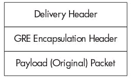
The specific standard for the GRE encapsulation is IP over -RFC 1702 and it is the standard supported by a switch. Use of this RFC 1702 standard is to route the IP packets between the Private internet protocol network across the internet which uses globally assigned IP addresses. The private IP network can either use IP addresses which ranges of the reserved IP addresses for the private network in the RFC 1597 or even worse, any randomly chosen range of the IP address.
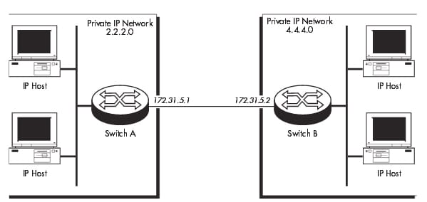
In the either case, the private IP network administration has to ensure that the packets using such type of IP addresses are not transmitted to the external network, to prevent the routing conflicts. The GRE allows the host in one private IP network mainly to communicate with the hosts in the other private IP network by providing the tunnel between the 2 switches across the internet. In the below example, the IP packet from a 2.2.2.0 private IP network destined for the host in the 4.4.4.0 private IP network are encapsulated by the switch A and also forwarded to the switch B. An intermediate switch will route the packet by using the address in a delivery protocol header. The switch B will extract the original payload packet as well as routes that to the appropriate destination within the 4.4.4.0 network.
The switch supports the RFC 1702, that defines the encapsulation of the IP packets over the internet protocol. Each switch which offers the GRe encapsulation defines 1 or more GRE entities. The entity may also contain the list of 1 or more patterns that specifes the source interface or mask/ source IP address and the target IP address. The entity is created by using the command as follows:
A switch supports both the multi point and point to point configurations. At the point to point configurations, 2 private networks connected over the internet through the single link and a GRE entity may be defined by using only source or interface and SMASK parameters. Any of the IP packet received from a source interface or else from a source IP address can be encapsulated by using the GRE and also forwarded to a target IP address.
In the multi point configuration, the multiple private network connected over the internet. Every private network has the multiple links to the other private network and the generic routing encapsulation entity has to be defined by using the SMASK, DMASK, SOURCE and DESTINATION parameters. Any of the IP packets gets from the mask and source IP address and the destined for a destination IP address and the mask, can be encapsulated by using the GRE and forwarded to a target IP address. Then the switch which is specified by a target address decapsulates a GRE packet, and also forward the IP packet to their destination. The IP packets that do not match any of the patterns in a GRE entity are treated as the normal IP packets and a process accordingly. The GRE entity can be associated with 1 or more IP interfaces. Anyhow, each IP interface can be associated with one GRE entity only. Any of the IP packets reached through an IP interface are checked against a pattern in a GRE entity and suppose the match is detected that the IP packets are encapsulated by using the GRE and forwarded to specified target addresses. The order in which pattern is listed in the GRE entity is the most important factor in the encapsulation process. The GRE encapsulation on the certain IP interface may be enabled, modified or disabled by setting a GRE entity to the NONE or the other entity number by using the SET IP INTERFACE= interface GRE={0..100|NONE}
The GRE encapsulation can be disabled or enabled for all the IP interfaces on a switch using the below command:
Disable GRE
Enable GRE
To configure the GRE follow the below steps:
Step 1:
Enable a GRE module
A GRE module has enabled on the switch B and Switch A by using the command enable gre on the each switch.
Step 2:
Create a GRE entity
The GRE entity has to create on the every switch to identify which of the IP packets are being encapsulated and also where to forward that encapsulated packets. On the switch A, create the GRE entity to match all the IP packets received from a 2.2.2.0 private IP network and forward it to switch B, by using the below command:
ADD GRE=1 SOURCE=2.2.2.0 SMASK=255.255.255.0
TARGET=172.31.5.2
On the switch B, create the GRE entity to match the entire IP packets received from a 4.4.4.0 private IP network an also forward it to the switch A by using the below command:
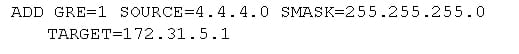
Step 3:
The GRE entity has to be associated with the IP interface before it turns active. It is an example that the GRE entities are associated with an Ethernet interface of the switch that is attached to a private IP network.
On switch B, the associate GRE entity with the IP interface eth0 by using:

On switch A, the associate GRE entity with the IP interface eth0 by using:

Step 4:
Assign a gateway for the local hosts
The local host on the each private IP network has to be configured to use an appropriate router as its gateway to a internet and other private IP network. The hosts in the 2.2.2.0 private network required to be configured to make use of the Switch A as its gateway and also the eth0 interface switch that has the 2.2.2.1 IP address. The hosts in the 4.4.4.0 private network required to be configured to make use of the switch B as its gateway and also the etho0 interface switch that has the 4.4.4.1 IP address./
Then the exact method based on the specific IP/TCP software used on a host, but for the IP/TCP software running on the PC, there may be the configuration file on a PC containing the link like as follows:

Verify the GRE:
To verify the configuration, it is required to ping the other end and force the VPN tunnel to start decrypting or encrypting the data:
In that, the command show crypto session will quickly verify the encryption.
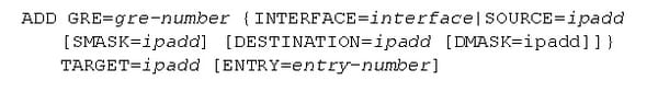
In this section, the commands available on a switch to configure and manage GRE as follows:
Gre-number is the decimal number which ranges from 0 to 99.
Interface is the interface name formed by simply concatenating the interface type.
Ipadd is the IP address in the dotted decimal notations
Entry-number is the non zero decimal number.
The above commands are mainly used to add the pattern to the GRE entity in an encapsulation table. Then the exact pattern will not already exist in a GRe entity. Those patterns comprises either the IP source address or interface name and the mask to match the IP packets against and the destination IP address for the matching packets. A GRE parameters indicate the GRE entity number to which a pattern has to be added.
The SOURCE parameter indicates the source IP address in the dotted decimal notation. The IP packets which originating from that IP address can be treated as the IP packets from the private IP address as well as can be encapsulated. This parameter can used with a SMASK parameter to denote the range of the IP addresses. The SMASK and SOURCE parameter should be compatible.
The INTERFACE parameter denotes the interface name used by an IP module. All the IP packets received through the interface can be encapsulated and also forwarded by using the GRE. If the INTERFACE is denoted, DMASK, SMASK, DESTINATION and SOURCE cannot be indicated.
The DESTINATION parameter indicates the destination IP address of a packet to be encapsulated in the dotted decimal notation. The IP packets which originating from an IP address indicated by a SOURCE parameter and destined for that IP address can be treated as the IP packets from the private IP address. The DMASK and DESTINATION parameters can be compatible. The DMASK parameter indicates a network mask, in the dotted decimal notations, to be used with an IP address's destination by a DESTINATION parameter to define the range of the IP address. The DMASK and DESTINATION parameter can be compatible.
The TARGET parameter indicates an IP address dotted decimal notation of the interface on the destination switch. An IP address can be valid global IP address. An encapsulated IP packets can be sent to that address.
Then the ENTRY parameter indicates the GRE entity entry number which the pattern occupies. The existing with higher or same entry number can be pushed down a list. If a number is merely greater than the number of the patterns in a list, then that pattern can be added to the end of a list. Then the default is to add a pattern to an end of a list.
The entry number is the non zero decimal number. The disable GRE disables the GRE encapsulation on a switch. The enable GRE is the command which enables the GRE encapsulation on a switch. The purge GRE resets the GRE encapsulation on a switch and also purges all the GRE configurations as well as patterns in the nonvolatile storage.
The GRE tunneling protocol is developed by the Cisco system that can encapsulate the wide variety of the network layer protocol inside the point to point links over the internet protocol internetwork. Tunneling offers the private, secure path for transporting the packets via a public network by encapsulating the packets inside the transport protocol is called as IP encapsulation protocol. The GRE is the IP encapsulation protocol, which is used transport packets through the network. The information is sent from the one network, to the other network through the GRE tunnel. It guides you how to configure and verify the GRE in this section.


Site Search:


